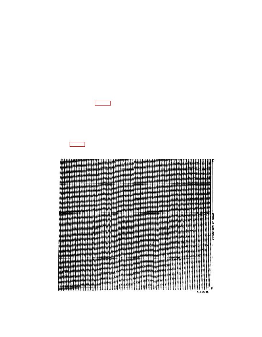
direction. If the rectangles are too small, turn
the pressure-plate screws, the recorder-
the lens barrel into the housing. If they are too
tube wires should be placed under the
large, turn the lens barrel out of the housing and
clamp so that they are captive, but free
tighten the locking ring. Move the drum to the
enough to slip and prevent cutting of the
extreme left and place a thin negative on the
insulation.
drum so that the negative is perfectly tight and
Caution: There are 250 volts dc on
extends one-fourth inch over the right-hand edge
the recorder-tube terminals.
of the drum: keep the emulsion side out. Adjust
d. Testing Alinement of Recorder Optical System.
the transceiver so that the meter indicates +2.
Set up for photographic reception and make a test
The image of the rectangle should be visible on
run on photographic paper or film. Recording
for 1 minute is required at the following levels:
the film beyond the edge of the drum. If it is not
-4, 2, 0, and +2 db, Develop the exposed
visible, remove the motor and clutch cover and
paper, examine it under a magnifying glass, and
push the drum farther to the left. If the readjust-
note how the rectangular images stack up on one
ment has caused the image to go out of focus,
another in sharpness and size (fig. 123). When in
loosen the screw in the clamp (L) which supports
the optical system. Carefully slide the optical
proper adjustment, the rectangles just touch one
system back and forth until the image is sharp.
another on all four sides. If the rectangular
A magnifying glass is necessary to see the image
images are not obvious to the naked eye at 8- to 10-
inch distance, the images can be considered satis-
clearly. It may be necessary to repeat this image
size adjustment several times to get satisfactory
factory. If the rectangles are obviously under-
results, Tighten screws and locking rings securely
sized or oversized, readjust the lens barrel.
after each adjustment. The square image should
e. Alinement of Recorder Optical System. Loosen
have two sides parallel to the axis of the drum.
the locking ring (I, fig. 122), and turn the adjusting
When focus adjustment is made, the optical system
ring (G) and lens barrel (H) 2 turns in the proper
165


