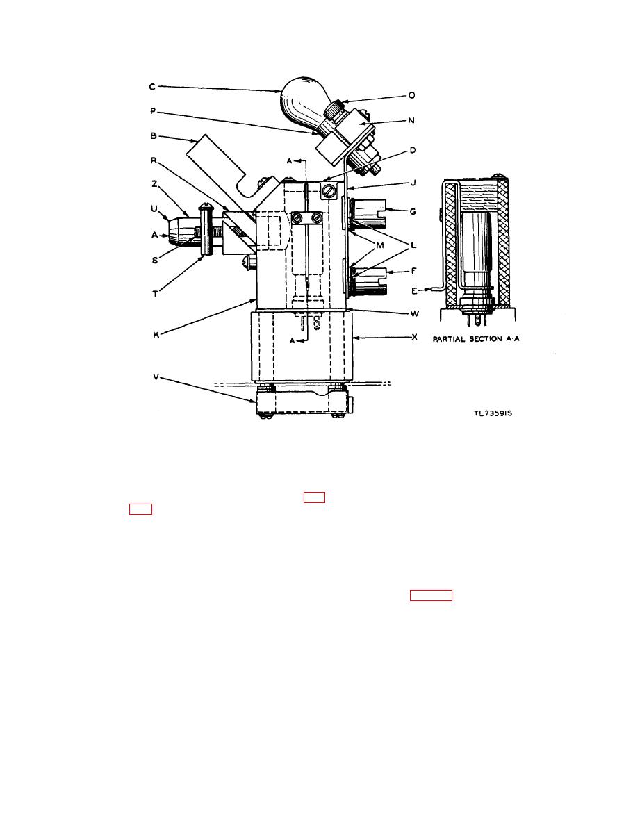
Figure 120. Transmitter optical system, Facsimile Transceivers TT-1/TXC-1, TT-1A/TXC-1, TT-1B/TXC-1, and
TT-1C/TXC-1.
the resistors. There should be a loud
65-line half-tone or very fine print. The 65-line
half-tone copy may be obtained from large news-
modulated signal in the phonea.
paper photographs having light gray or white
(6) The focus of the exciter lamp is adjusted
background. Connect a headset across the line
by loosening the locking screws (O, fig.
terminals. If the tone is not loud enough, use
until the sharpness of the light spot on
the LINE JACK. Listen to the signal as the
drum rotates; move the lens barrel in and out
white paper on the drum is a maximum.
until the sharpest and loudest modulation tones
The horizontal and vertical position of
are heard. To make the modulation tones dis-
the light spot relative to the lens barrel
tinct, the 1,800-cycle carrier can be cut off by
(Q) is controlled by the knobs (AA) and
shorting terminals 1 and 2 of T5. Keep the line
(II) which can be turned after the lock-
or indicator (U, figs. 120 and 121) in the top posi-
nuts (E) and (EE) have been loosened.
tion. At the point of loudest or sharpest tone,
The desired vertical position of the spot
lock the lens barrel in position. Again. set the
will be indicated by a dip of the DB
adjustments of the exciter lamp position with the
METER as a thin horizontal line drawn
cam screws. Replace the white sheet on the drum
on the white paper reaches a point about
for a final check. An alternate method of alining
one-third of the way down from the top
the photocell lens barrel is to connect an oscillo-
of the spot. This is done with the
scope across the line terminals and move the drum
transceiver set for maximum contrast
by hand, alternately scanning black and white
(minimum signal on black).
copy. Adjust the lens barrel for maximum con-
i. Photocell Lens Barrel. Remove the white
paper from the drum and replace it with a sheet of
trast between black and white, as indicated on the


