(5) Place the rubber ring (F) on the bulb of
Ref
the new recorder tube and reassemble
Function
Name of part and description
symbol
--.
.
..--
..-
.--
.- ..- .--
the system; leave the four pressure-plate
screws loose.
Calmp for phototube
DD
CLAMP, socket . . . . . . . .
socket (CC).
(6) Connect the recorder-tube leads to the
Pivot and locking
EE
STUD, threaded.. . . . . .
prongs, the red lead (+) going to the
studs for eccentric
No. 7 prong which is nearest the alining
gear (H).
projection. (Most sets have a socket,
Tube clamp and vi-
FF
CUSHION . . . . . . . . . . . .
not individual connectors.)
bration dampener.
Converts fluctuations
GG
PHOTOTUBE: type 5652.
(7) Connect the UC coupling coil to the
in light intensity
transceiver and place the coil near the
entering phototube
motor.
into fluctuations in
(8) Turn the selector switch to RECORD
electrical resistance
to amplitude-mod-
PHOTO.
ulate a carrier.
(9) Adjust the GAIN control and the posi-
Electrostatic shield
HH
SHIELD, phototube and
tion of the UC coupling coil until the
for phototube leads.
grid connection.
meter indicates about +2 db.
Knob for adjusting
II
KNOB ----------------
(10) Move the drum to the extreme right
lateral and horizon-
and shade the transceiver from direct
tal position of ad-
justing plate (J).
light; slip a piece of tissue paper or a
Locks socket holder
JJ
SCREW, locking -------
piece of undeveloped film in front of the
in correct focusing
recorder optical system, close to the
position.
objective lens. A ring of light should be
.----
--
visible on the tissue or film. This ring
must be within the field of the lens,
preferably in the center. If the light is
off to one edge so that some of the light
a. General. Failure to obtain recordings of
is being shut off by the lens barrel or the
sufficient density, in most cases, can be traced to
light is not visible at all, orient the
a weak recorder lamp. Check the current that
recorder tube by pressing on the retainer
goes through the recorder lamp and make a test
cup in different directions to center the
with a replacement lamp before suspecting faults
ring of light well within the confines of
in the optical system.
the objective lens. Once the ring of light
b. Cleaning Lenses. The lens surfaces, with the
is centered, tighten the plate screws
exception of the front face of the objective lens
progressively and recheck the ring of
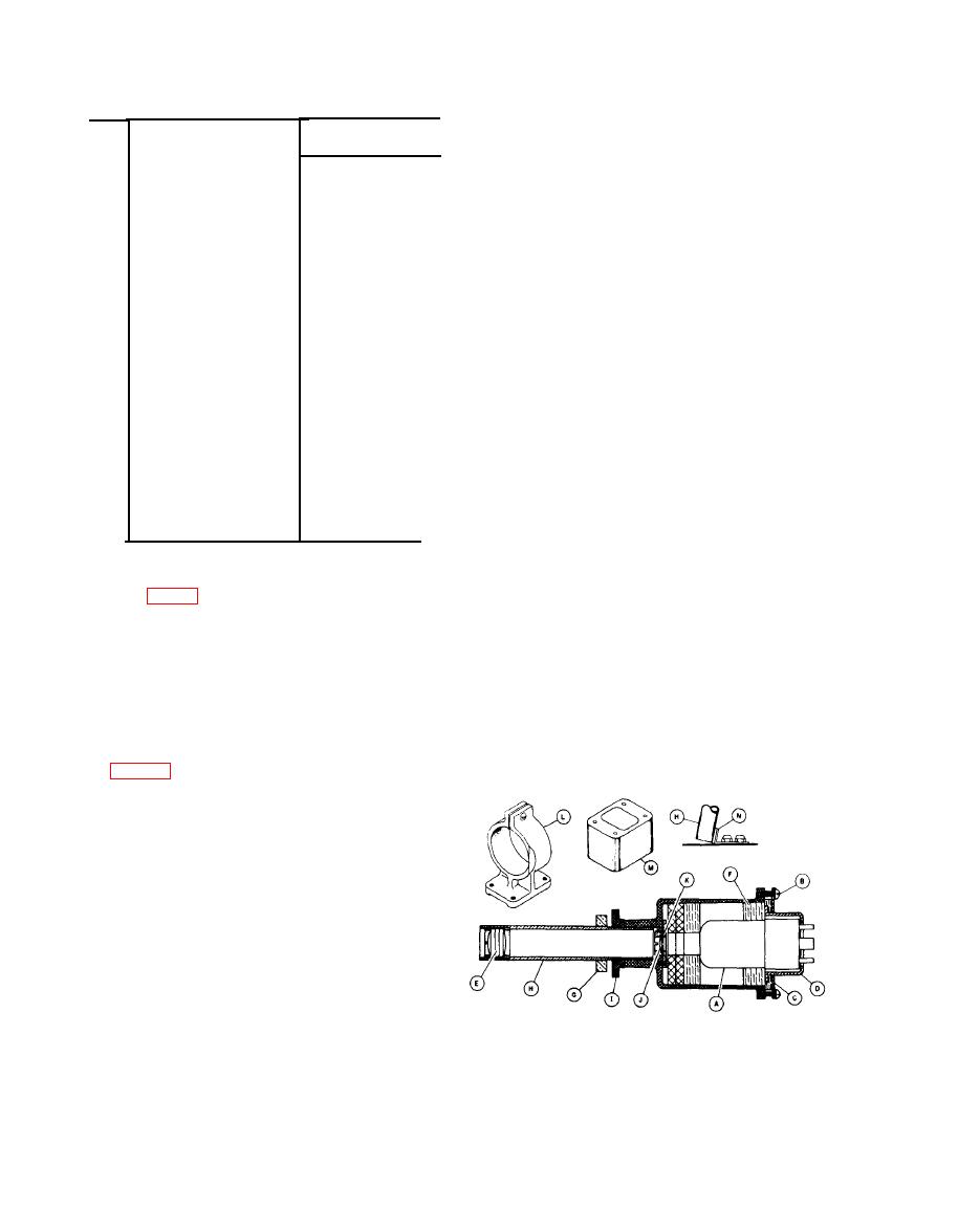
(E, fig. 122) are protected. Dust usually can be
light. If there is a clamp under one of
removed with a camel's-hair brush without tam-
pering with the adjustments of the optical system.
c. Recorder Lamp Replacement. The recorder
lamp can be replaced without removing the
recorder lamp optical system from its bracket in
the following manner:
(1) Remove connectors or sockets from the
recorder lamp (A).
(2) Remove the four screws (B) at the rear
of recorder optical system.
(3) Remove the pressure plate (C) and
sleeve (D).
(4) Pull the lamp (A) carefully out of the
optical system. If the lamp comes out
NOTE:
LENS
J
IS
OMITTED
IN
FACSILIE
TRANSCEIVERS
TT-1C/TXC-1,
TT-10/TXC-1,
AND
TT-1E/TXC-1
without the rubber ring (F) around the,
bulb, remove the rubber ring from the
TM
2258-36
inside of the optical system.


