TM 5-2420-224-20-2
FRONT LOADER/FORKLIFT CONTROL VALVE CONTROLS
REPLACEMENT AND ADJUSTMENT
This task covers:
a. Removal b. Installation c. Adjustment
General Safety Instructions:
Tools and Special Equipment:
Tool Kit, SC 5180-90-CL-N26
Materials/Parts:
Pin, Cotter (2)
Personnel Required: (2)
Equipment Condition:
Reference
Condition Description
Page 4-390 or 4-391
Spare Tire and Mount
Removed (SEE or
HMMH)
W A R N I N G
Do not connect or disconnect
any electrical connector unless
v e h i c l e M A S T E R d i s c o n n e c t
switch is OFF. To do so could
result in injury to personnel.
1.
2.
3.
4.
5.
6.
NOTE
Procedure is the same for both
vehicles except as noted.
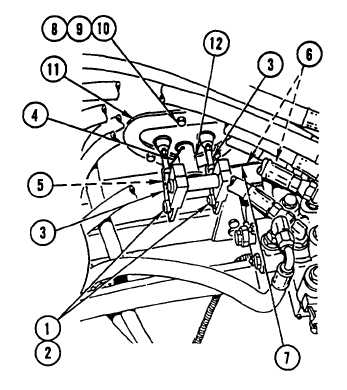
REMOVE two hitch pin clips (1) and two
PINS (2) and DISCONNECT two CLEVISES
(3).
NOTE
Perform step 2 on HMMH only.
DISCONNECT CABLE (4) from cable (5).
REMOVE two BOLTS (6) from lever bracket
(7).
REMOVE three nuts (8), three capscrews (9),
three washers (10), seal assembly plate (11),
and front loader/forkIift control LEVER
assembly (12).
REMOVE two cotter pins (13) and two PINS
(14) and DISCONNECT two CLEVISES (15).
DISCARD cotter PINS.
REMOVE ROD (16) from boom handle block
(17).
4-532


