TM 5-2420-224-20-2
BACKHOE CONTROL ROD ADJUSTMENT
This task covers:
Adjustment
Applicable Configuration:
Equipment Condition:
SEE
Reference
Condition Description
Tools and Special Equipment:
Page 2-22
Backhoe in Three-Point
Shop Equipment, SC 491 O-95 -CL-A74
Stance
Toot Kit, SC 5180-90-CL-N26
Page 4-404
Backhoe Control Tower
Removed
Materials/Parts:
Pin, Cotter
1.
2.
3.
4.
5.
6.
NOTE
Procedure is the
control rods.
same for all
Make sure control valve spool is
in neutral position.
Make sure control levers are
e v e n w i t h e a c h o t h e r a n d
centered in opening of cover.
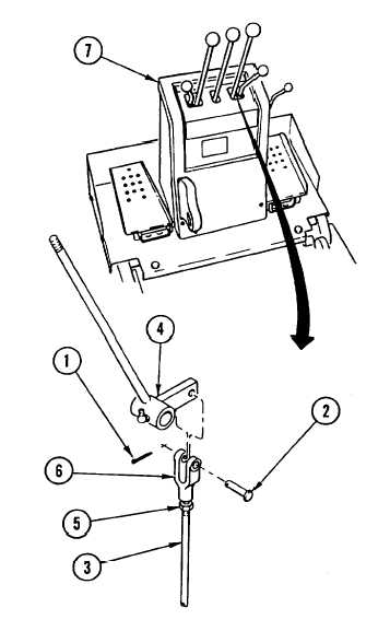
Remove cotter pin (1) and pin (2) from control
rod (3) and control lever (4). Discard cotter
pin.
Back off nut (5) and turn clevis (6), as
needed, for proper length.
Temporarily install pin (2) through control rod
(3) and control lever (4).
Temporarily install cover (7) to check for
proper position in opening.
Remove cover (7) and perform steps 1 thru 4,
as needed, for proper adjustment.
When adjustment is complete, remove cover
(7), tighten nut (5), and install new cotter pin
(1).
NOTE
Follow-on Maintenance:
Install backhoe control tower (page
4-404).
4-531