TM 11-5895-1412-12&P
Section III.
OPERATING PROCEDURES
Page
System Configuration . . . . . . . .
Entering System Configuration . . . .
Entering Datacom Configuration . . .
Laserjet Configuration and Connection
Connecting the Laserjet . . . . . . .
Serial Port Connection . . . .
Entering System Configuration
Entering Datacom Configuration
. . . . . . . . . . . . . . .
2-8
. . . . . . . . . . . . . . .
2-8
. . . . . . . . . . . . . . .
2-9
. . . . . . . . . . . . . . . 2-10
. . . . . . . . . . . . . . . 2-10
. . . . . . . . . . . . . . . 2-10
. . . . . . . . . . . . . . . 2-11
. . . . . . . . . . . . . . . 2-11
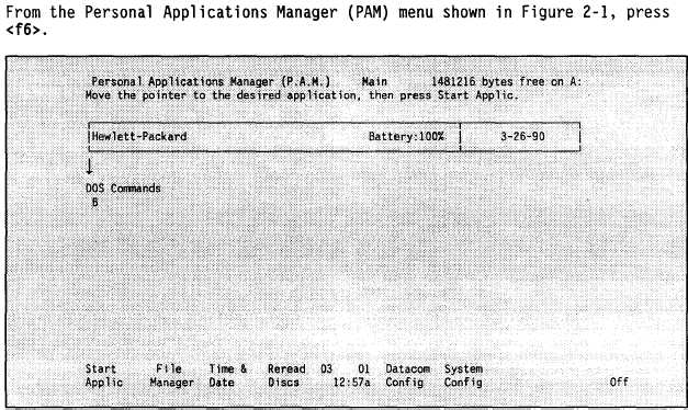
It is essential that correct system configuration information is loaded into
the BGU prior to operation of any input functions. System configuration
determines how the read/write memory is divided between the system and disk
drive; how the automatic timeout works (when the recharger is not connected);
what the cursor looks like; how characters look on the screen display; what
happens when a key is pressed; and how the computer communicates with system
components.
Figure 2-1
If a disk is present in the disk drive, this screen may look different.
2-8