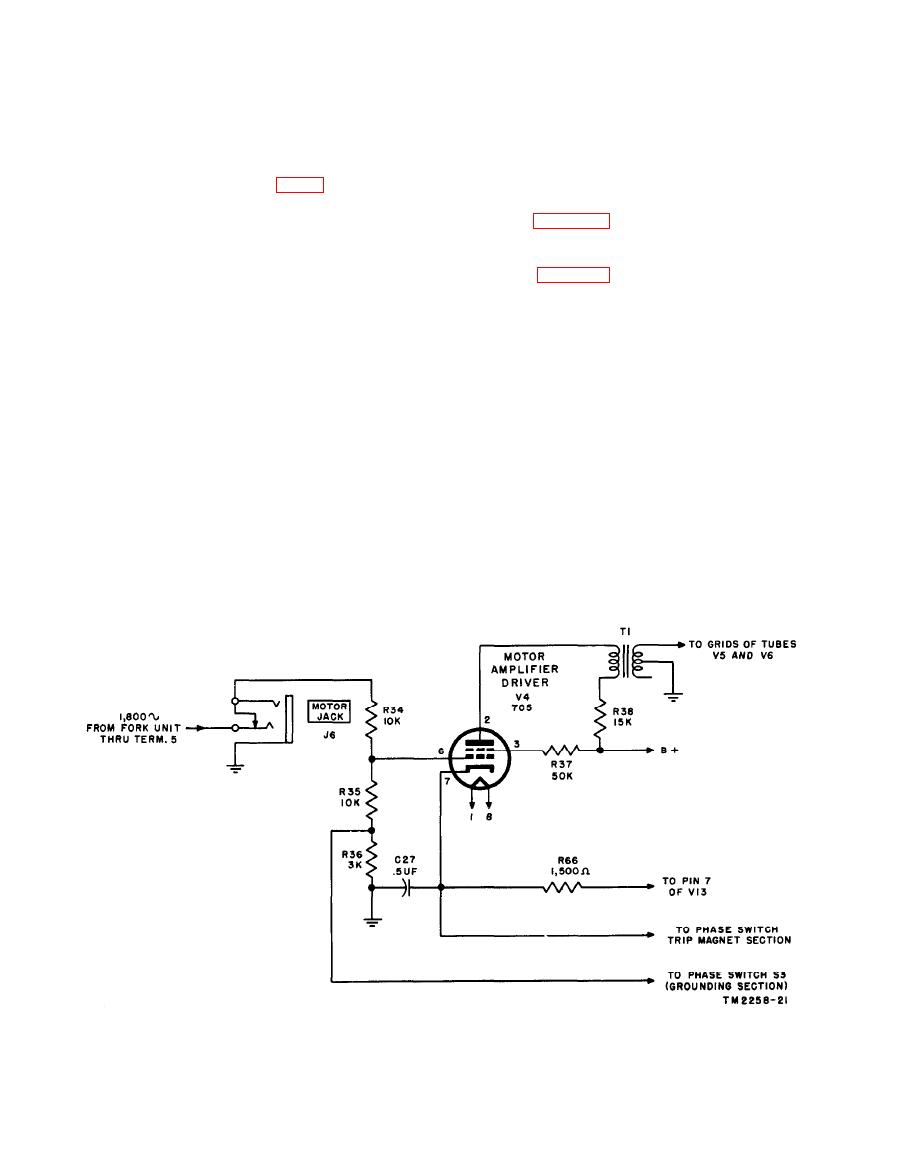
motor. Input to the motor amplifier stage V4
nism. During normal operation, with
is approximately 25 volts. The voltage across
the PHASE switch released, cathode
the motor, however, may be as high as 1,000 volts.
current of V4 flows through the phasing
magnet coil associated with trigger tube
a. Motor Amplifier Driver.
(1) Facsimile Transceivers TT-1/TXC-1 and
V16 and also through the series resistor
combination, R66 and R67 (stage V13),
cycle signal of the fork oscillator unit is
which is in parallel with this coil. (Refer
applied to the grid of the motor amplifier
to figures 48 and 49 and the over-all
driver stage V4 (7C5). This signal is
schematic diagrams of Facsimile Trans-
applied through terminal 5 of the fork
ceivers TT-1/TXC-1 and TT-1A/TXC-
oscillator terminal board through MO-
1 (figs. 163 and 164).) The flow of
TOR JACK J6 and is applied to a
current through the coil holds the arma-
voltage divider consisting of R34, R35,
ture against the phasing magnet so that
and R36. Normally, the junction be-
it does not actuate the clutch mechanism
tween resistors R35 and R36 is shorted
used in the phasing operation. The flow
to ground so that R36 is out of the cir-
of current through R67 adds to the bias of
cuit. The voltage across R35 is applied
tube V13, which requires bias beyond the
to the tube control grid (pin 6). During
cut-off value. During the phasing opera-
the phasing operation, however, R36
tion, the phasing magnet is disconnected
becomes part of the voltage divider, and
from the cathode circuit of V4, and the
the voltage to the grid of tube V4 is
armature is released. To compensate
increased. Increasing the input to V4
for the removal of the phasing magnet
results in increasing the drive on parallel
coil from the cathode circuit, resistor R40
motor amplifier tubes V5 and V6, fur-
is connected in parallel with the series
nishing additional power to the synchro-
combination, R66 and R67, during the
nous motor. During the phasing oper-
phasing operation. Capacitor C27 is the
ation, the motor requires additional
cathode bypass capacitor for tube V4.
power because of the additional load
Screen and plate voltage is applied from
created by friction in the clutch mecha-
the +450-volt supply through screen


