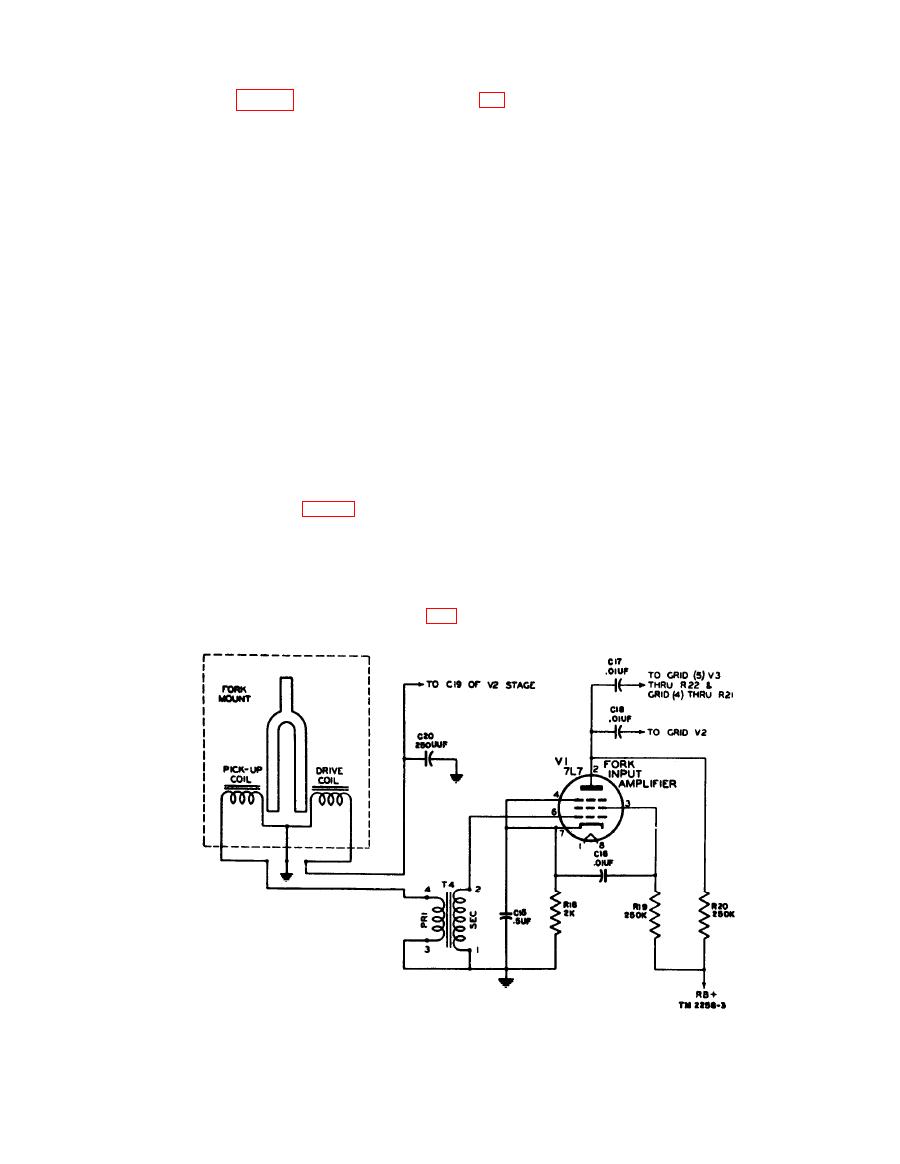
a type 7C5 tube, amplifies the output of V1 and
from affecting the fork oscillator.
(1) Motor amplifier buffer. Pins 2, 3, and 4
supplies feedback energy to the drive coil which
of tube V3 comprise the motor amplifier
keeps the fork vibrating. One of the requirements
buffer. The grid receives 1,800-cycle
for frequency stability is 8 constant output from
energy from the plate of V1 through
this stage to the fork drive coil. The grid is
coupling capacitor C17 and limiting
driven so hard that variations in amplitude at
resistor R21. Resistor R27 serves as
the input have practically no effect on the output.
the grid return and the grid is bypassed
The output from the plate of V1 is coupled to the
grid of V2 (pin 6) through C18, with R23 serving
for high frequencies by C21. Cathode
resistor R28 is left unbypassed to pro-
as the grid return. Cathode resistor R24 and
vide degeneration. Plate voltage is ap-
variable resistor R25 are left unbypaseed to
plied to pin 3 from the regulated +250-
provide degenerative feedback in this stage,
volt supply through plate load resistor
giving a stabilizing effect on the output. Resistor
R23. Output from the plate is coupled
R25 is variable to permit minor adjustments in
through C23 to the motor amplifier
frequency of the fork oscillator to compensate
driver stage (V4) via the MOTOR
for extreme variations in temperature, or changes
JACK. Capacitor C23 also couples
in value of circuit components. The plate and
1,800-cycle energy to the exciter lamp
screen are connected together for triode operation.
amplifier circuit in Rectifier Power Unit
Plate voltage is applied through plate load resistor
P P - 8 6 ( * ) / T X C - 1 through pin 9 of
R26 from the regulated +250-volt supply. The
plug P1 . A connection from C23 to
output voltage developed across R26 is coupled
section 3 of selector switch S1 short-
back to the fork drive coil through capacitor C19.
circuits the 1,800-cycle supply to the
motor circuit and the exciter lamp
(V3), using a type 7N7 dual triode, consists of two
circuit when the switch is in the STAND-
buffer amplifiers fed by the fork input amplifier
BY position.
V1, and supplies an 1,800-cycle signal to the
(2) Modulutor buffer. Pins 5, 6, and 7 of
motor amplifier stage V4, the exciter lamp ampli-
tube V3 comprise the modulator buffer.
fier circuit in Power Supply PP-86(*)/TXC-1,
The grid also receives 1,800-cycle energy
and the photocell bridge modulator circuit (fig.


