pulses to the phase amplifier circuit, which oper-
aperture to the photocell and bridge modulator
ates the phase magnet and clutch during the phas-
where varying light intensities are converted into
ing process just before each picture transmission.
varying electrical signals. These signals ampli-
The fork oscillator unit serves a single purpose on
tude modulate the 1,800-cycle carrier signal sup-
receiving. It generates an 1,800-cycle signal
plied from the fork oscillator unit. This modu-
which is amplified to operate the synchronous
lated signal is amplified in the voltage amplifier.
motor at the same speed as the motor in the trans-
The level is established at this point by the GAIN
mitting transceiver.
control and is indicated on the DB METER.
The signal is boosted further by the power ampli-
1D/TXC-1, TT-1E/TXC-1, and TT-1F/TXC-1
fier before going out on the line. The fork oscil-
contain a multivibrator circuit which is used only
lator unit, in addition to furnishing the carrier
when operation at half-normal speed (30 drum
signal to the photocell bridge modulator, supplies
rpm) is desired. The multivibrator is switched
an 1,800-cycle voltage which is amplified in the
into the motor circuit by operation of motor speed
control switch (30RPM-60RPM) S4. For half-
U n i t PP-86(*)/TXC-1. The output of this
speed operation the 1,800-cycle signal voltage
circuit supplies 6 volts at 1,800 cycles to the
from the fork oscillator unit locks in the 900-cycle
exciter lamp to maintain it at a constant brilliancy.
multivibrator, the output of which is applied to
Another portion of the 1,800-cycle fork oscillator
the synchronous winding of the motor through
output is amplified in the motor amplifier circuit
the synchronous motor amplifier. Motor cur-
for operation of the synchronous motor which
rent is indicated on the MOTOR CURRENT
drives the drum at a constant speed. The voltage
meter. Application of an external signal voltage
regulator supplies a regulated +250 volts to the
in the MOTOR JACK permits operation of the
critical transceiver circuits.
recording drum at any speed between 30 and
d. Receiving. Functions of the various stages
100 rpm.
in the receiving transceiver are shown in figure 32.
The signal from the line is set to the proper operat-
circuit is included in all models of the transceiver
ing level by the GAIN control, then amplified in
except Facsimile Transceiver TT-1/TXC-1, and
the voltage amplifier and the power amplifier.
is energized when the selector switch is at STAND-
The DB METER, driven by the meter amplifier,
BY, For normal reception of voice over this
indicates the relative level of the signal being used
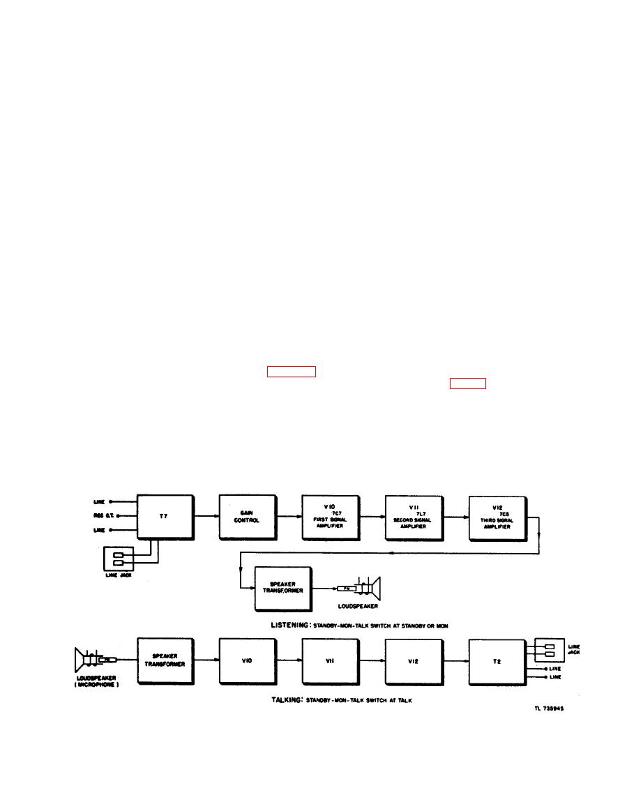
circuit, the STANDBY-MON-TALK switch is
for recording. The power amplifier drives either
at MON (if the motor is to be in operation) or at
the recorder lamp for photographic recording, or
STANDBY (if the motor is not to be in operation).
the recording stylus for direct recording. Another
In either of these positions, the signal from the
connection from the power amplifier sends phasing


