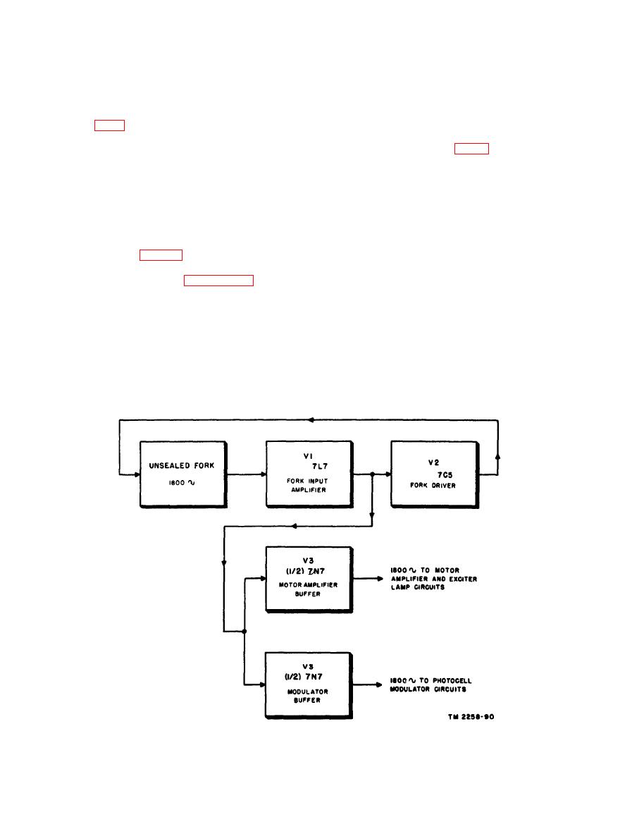
Section Il. FACSIMILE TRANSCEIVER TT-1(*)/TXC-1
stage through a transformer. The fork thus be-
comes a feedback unit that controls the frequency
Oscillator Unit
in the oscillator circuit composed of the fork,
V1, and V2.
The fork oscillator unit generates a highly
stable 1,800-cycle audio signal to supply the
V1 using a type 7L7 tube, amplifies the small
photocell bridge modulator circuit, the motor
oscillations from the tuning fork and drives tube
amplifier circuit, and the exciter lamp circuit.
V2, the fork driver, and also the two output buffer
The unsealed unit, used in Facsimile Transceiver
sections of V3. Energy from the fork pick-up
TT-1/TXC-1 only (serial numbers up to 105 on
coil is coupled through transformer T4 directly
order No. 2695-MPD-45), consists of three
to the grid of V1 (pin 6). Transformer T4 steps
stages: a fork input amplifier (V1), a fork driver
up the voltage from approximately .4 volt to 1.0
(V2), and a dual tube (V3) whose sections serve
volt. The tube is biased by the flow of plate
as output buffers (figs. 35 through 37). All three
current through cathode resistor R18 which is
stages are supplied regulated B+ voltage. The
bypassed by C15. Screen and plate voltage is
sealed unit is described in paragraph 70.
applied through screen dropping resistor R19 and
a. Tuning Fork. The frequency-determining
plate load resistor R20 from the regulated +250-
device is a bimetallic tuning fork with a natural
volt supply. The screen is bypassed to cathode
period of vibration of 1,800 cps. The fork is
by C16 to improve the stability of amplification
kept in vibration by a drive coil which is fed an
in this stage. Sine-wave voltage developed across
1,800-cycle signal of constant amplitude from the
R20 is coupled from the plate through capacitor
fork driver stage. A second coil, a pick-up coil,
C18 to the grid of V2 (pin 6) and through C17
is coupled to the vibrating fork so that the fork
to the output buffers. C20, a bypass capacitor
vibrations generate an 1,800-cycle ac in the coil.
across the fork drive coil, suppresses harmonica of
the 1,800-cycle signal.
This coil feeds the grid of the fork input amplifier


