JACK J6 to the grid of motor amplifier driver
tube V4.
TT-1D/TXC-1, TT-1E/TXC-1, and
TT-1F/TXC-1 only)
Tube V26 operates as a multivibrator. In this
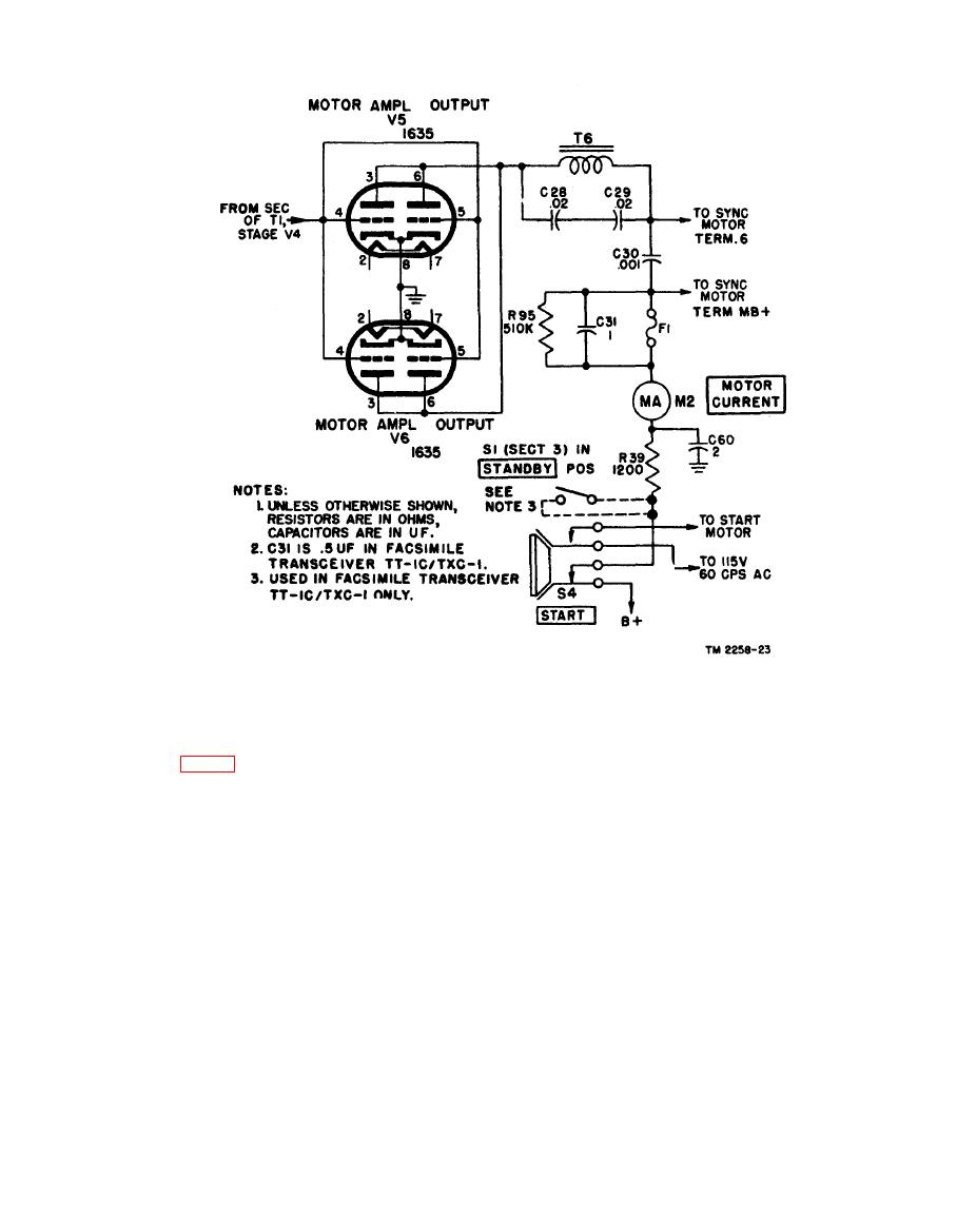
Transceiver TT-1(*)/TXC-1 is held at a constant
circuit, a portion of the output of one section of the
speed of 60 rpm by the 1,800-cycle power supplied
7N7 tube is fed into the input circuit of the other
by the plate circuit of motor amplifier output
section. While one section conducts, the other sec-
tubes V5 and V6. A worm gear on the motor
tion is cut off. The fork unit 1,800-cps output is
shaft is meshed with a gear which drives the lead
fed to the plates of the 7N7 through C65 and R99.
screw at 60 rpm through the clutch mechanism.
The values of C66, C67, R103, and R104, together
The motors originally used in Facsimile Trans-
TT-1A/TXC-1
with the internal capacitances of the tube, deter-
and
c e i v e r s TT-1/TXC-1
mine the frequency and rate at which each section
operated on 9-volt, 60-cps, ac, which was supplied
conducts. The output is taken from the plate
by Rectifier Power Unit PP-86/TXC-1. These
(pin 3) through C64. The multivibrator natural
motors have been replaced with 115-volt ac
output (output without synchronization signal) is
operated motors, and the circuitry of the trans-
slightly less than 900 cps; the 1,800-cps signal
ceiver and rectifier unit has been modified accord-
locks it at exactly 900 cps. Switch S4 selects
ing to MWO SIG 11-2258-2. Facsimile Trans-
either the multivibrator output or the fork unit
ceivers TT-1B/TXC-1 through TT-1F/TXC-1
output directly and applies it through MOTOR
contain motors that operate on 115-volt, 60-cps.


