(2) Facsimile Transceivers TT-1B/TXC-1
(3) Facsimile Transceivers TT-1D/TXC-1.
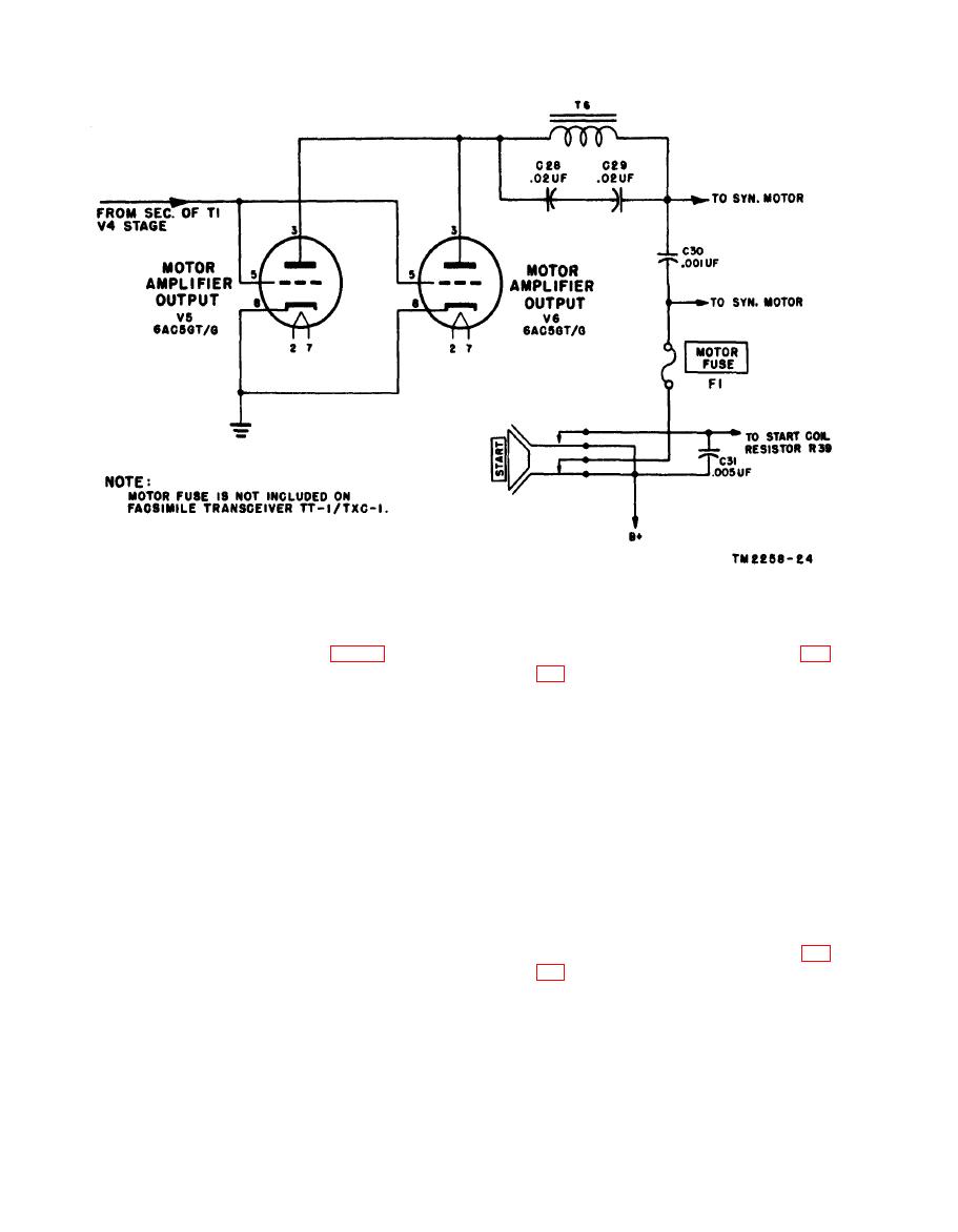
TT-1E/TXC-1, and TT-1F/TXC-1 (fig.
models operate the same as Facsimile
Transceivers TT-1/TXC-1 and TT-1A/
T X C - 1 , TT-1E/TXC-1, and TT-1F/
TXC-1 except for the following changes:
TXC-1, MOTOR CURRENT meter M2
(a) Bypass capacitor C31 in parallel with
is in the cathode circuit instead of the
resistor R95 is placed across MOTOR
plate circuit of the motor amplifier output
F U S E F1. MOTOR CURRENT
stage. The plate circuit is modified so
meter M2 indicates necessary adjust-
that when the 30RPM-60RPM speed
ments of the motor current.
change switch, S4, is in the 60RPM
(b) Series resistor R39 limits the motor cur-
position, C28 and C29 in series are across
rent, and bypass capacitor C60 keeps
T6 for 1,800-cycle operation of the syn-
this part of the circuit at ac ground
chronous motor. When S4 is in the
potential. A connection from R39 to
30RPM position, C28 and C29 in series
START switch S4 stops the motor in
are across the synchronous motor and
Facsimile Transceiver TT-1C/TXC-1
T6 is shorted for 900-cps operation of the
when selector switch (S1) is operated
motor.
to the STANDBY position. This
connection is made through the front
section of S1, disconnecting the +450-
capacitor C69 has been added to prevent
volt supply from the motor circuit
interned arcing in motor amplifier tubes
when the selector switch is operated to
V5 and V6 by reducing peak voltages in
the STANDBY position.
the 60RPM position.
82


