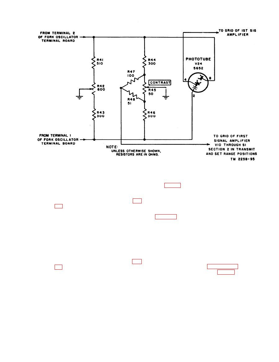
Figure 49. Photocell bridge modulator, Facsimile TranseiversTT-1D/TXC-1, TT-1E/TXC-1, and TT-1F/TXC-1.
and makes possible the use of an in-
creased 1,800-cycle input into the
bridge.
Facsimile Transceiver TT-1(*)/TXC-1 has five
(2) Facsimile Transceivers TT-1D/TXC-1,
stages of signal amplification. Various stages are
used for various functions, as determined by the
setting of the selector switch and as illustrated
photocell in these units. Resistor R49
in figure 76. Tubes V10, V11, and V12 are Class
is not used and the regulated +250 volts
A signal amplifiers. The first half of V13 is
is not needed since this tube operates
operated as a Class C threshold limiter and serves
linearly without the injection of fixed
as a driver for V14, a Class B output amplifier.
bias. Capacitor C58 is not used since
Tubes V10 and V11 are used for all functions,
the null point can be closely adjusted
V12 on TRANSMIT and RECORD PHOTO,
in these models (because of the operating
V13 on RECORD DIRECT, and V14 on RE-
characteristic of photocell tube 5652)
CORD DIRECT and RECORD PHOTO posi-
with the slide arm of R42 connected
tions. The use of V10, V11, and V12 in the talk-
directly to ground. Resistor R50 (fig.
back circuit is explained in paragraph 78.
side connecting both to the cathode of
This stage is a high-gain pentode voltage ampli-
the photocell and to the grid of V10.
fier, tube 7C7 (tube 5879 in Facsimile Trans-
Its low potential side is returned to
ceiver TT-1E/TXC-1 and TT-1F/TXC-1), bi-
ground through R47, R48, and R45,
ased for Class A operation and used for both trans-
when selector switch S1 (section 3) is in the
mitting and receiving.
TRANSMIT or SET RANGE position.
On other settings of the selector switch,
(1) Transmitting. With the selector switch
the bridge circuit continuity is inter-
at TRANSMIT or SET RANGE, the
rupted.
grid of V10 is fed by the photocell bridge


