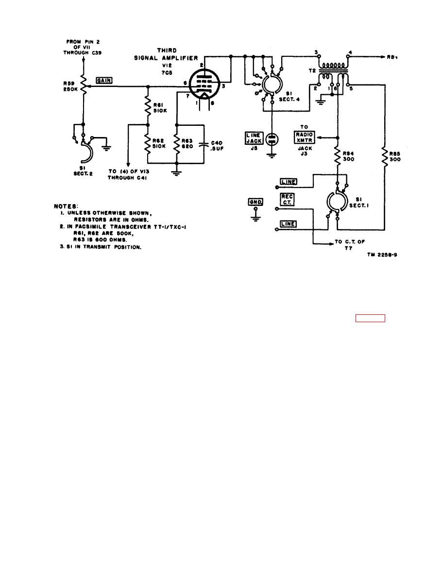
direct amplifier (V13, section 5-6-7) is
connected to the LINE binding posts
completed through the primary of trans-
through sections IR and IL and attenu-
former T2 and section IVR of the selector
ator resistors R84 and R85. In the set
switch, with secondary No. 1 of T2 con-
RANGE position of the selector switch,
nected to the grid circuit of V14.
the LINE binding posts and the LINE
JACK are disconnected, and secondary
56). This stage uses dual-triode tube 7N7. Sec-
No. 1 is short-circuited and grounded.
tion 5-6-7 serves as the Class C RECORD
(2) Receiving. When the selector switch is
DIRECT amplifier-driver stage which drives
at any other position than TRANSMIT
stage V14. Pins 2, 3, and 4 serve as the meter
or SET RANGE, the low side of R59
amplifier, providing a vacuum-tube voltmeter cir-
( t h e output GAIN control) is un-
cuit for measuring input and output signal levels
grounded, removing its effectiveness as a
in decibels.
gain control but still permitting V12 to
be fed by V11. Tube V12 serves as a
(1) Record direct amplifier driver. Although
received signal amplifier only for photo-
the grid (pin 5) of the first section of tube
graphic recording. With the selector
V13 is fed a modulated 1,800-cycle signal
switch in RECORD PHOTO position,
at all times, the stage is operative only
the plate circuit of V12 is established
when the selector switch is in the REC-
through the primary of transformer
ORD DIRECT position. The stage is
T2 and through section IVR of the selector
operated as a threshold limiter; that is,
switch. Secondary No. 2 of T2 is open-
it is biased considerably beyond cutoff
circuited, but secondary No. 1 of T2 is
and prevents an output signal until the
in the grid circuit of V14, the output
input signal reaches a predetermined
amplifier for recording. With the selec-
level. This is advantageous in control-
tor switch in the RECORD DIRECT
ling the signal used on direct recording.
position, the plate circuit of the record
The grid (pin 5) is fed from the plate of


