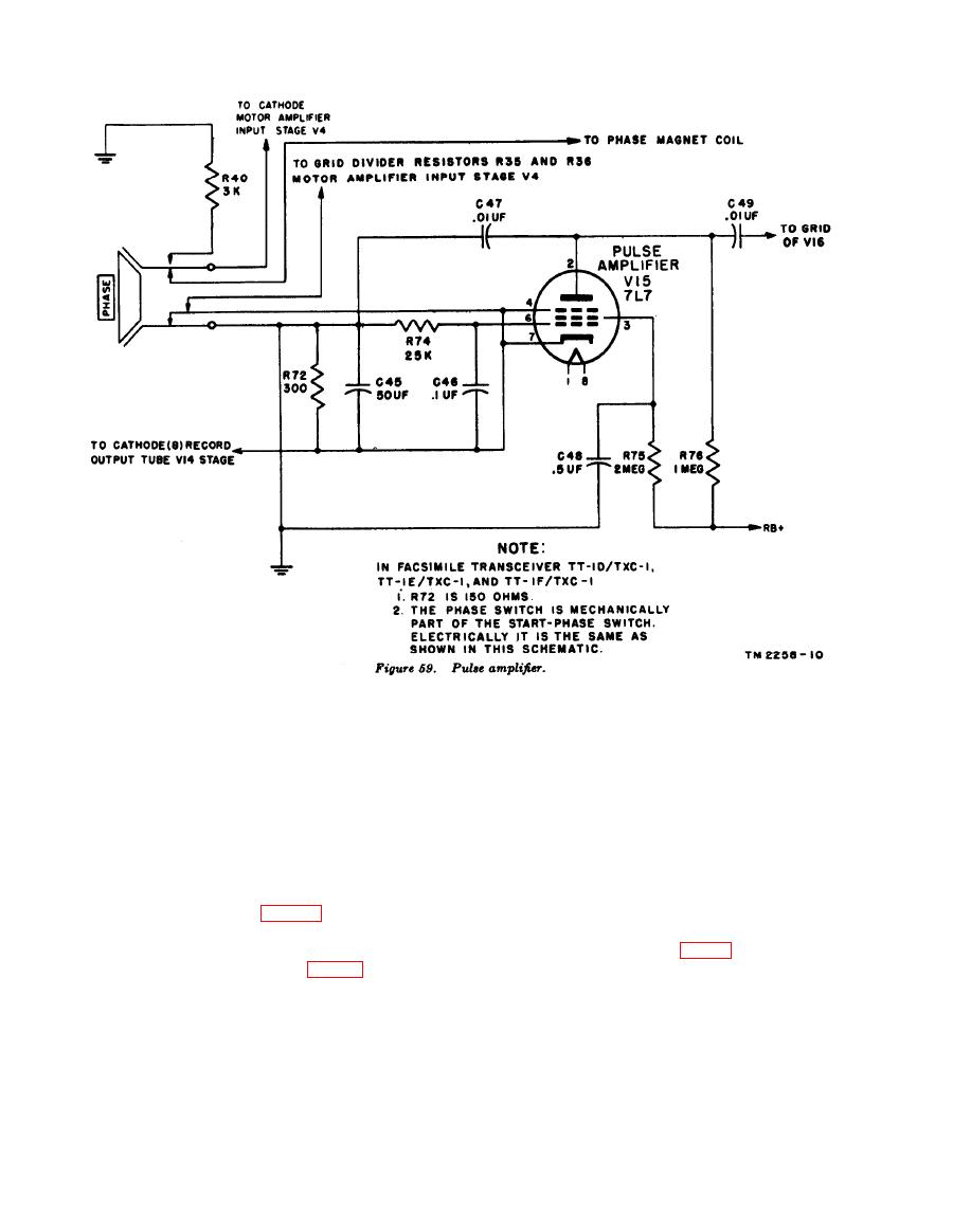
of tube V14 and the recorder lamp. The 1,800-
switch is pressed. Pressing this switch makes
cycle component is removed by a filter (C45, C46,
the following circuit changes:
C47, and R74) in the input circuit of V15. This
(1) Removes the phasing magnet from the
tube amplifies the pulse, which is applied to the
cathode circuit of V4, stopping the flow
input of thyratron trigger tube V16. Each pulse
of holding current through the magnet.
causes V16 to arc, pulling the armature to the
The magnet armature then engages the
phasing magnet and releasing the primary clutch
stop arm on the clutch, causing the
stop arm. The transmitter sends the phasing
receiving drum to rotate slower than
pulse just as the stop arm on the transmitting
the transmitting drum.
machine is passing the phasing magnet. Since
(2) Substitutes R40 in the cathode circuit of
the receiving stop arm is released by the phasing
V4 to compensate for the removal of the
pulse at this same instant, the transmitting and
phasing magnet (par. 71).
receiving transceivers are phased.
(3) Disconnects the short circuit across R36
in the grid circuit of V4, providing
uses a type 7L7 tube as a pulse voltage amplifier
increased drive to V4 (par. 71).
in an inverted circuit. When the PHASE switch
(4) Disconnects the short circuit across R72,
is operated, the pulse voltage developed across
coupling stage V14 into stage V15.
b. Electrical Circuit. The phasing pulse re-
R72 (cathode resistor of V14) is applied between
the cathode and the grid of V15. The cathode
ceived over the facsimile circuit is amplified by
of V15 is at signal input potential, and the grid
stages V10, V11, V12, and V14 of the receiving
is at ground potential for signal input. The
transceiver, and is rectified by the combination


