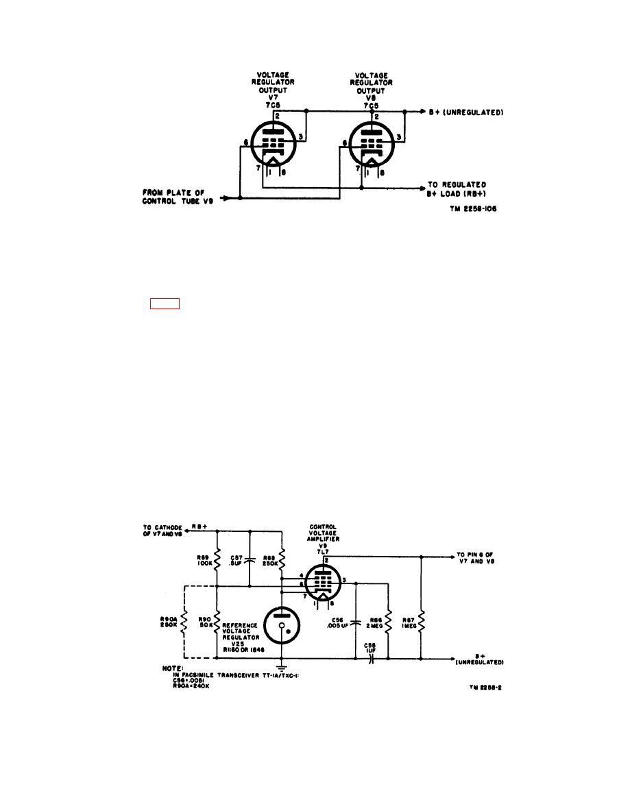
causes V9 to conduct more current, producing a
b. To understand the functioning of the circuit
in Facsimile Transceivers TT-1/TXC-1 and TT-
greater voltage drop across plate load resistor
R87. The voltage change at the plate of V9 is in
1A/TXC-1, assume that the +250-volt output of
a negative direction, and is greater in magnitude
the regulator suddenly changes to some higher
than the voltage change in a positive direction on
voltage because of line or load changes. The grid
the grid. This increased negative voltage at the
bias on tube V9 (fig. 64) is the difference in poten-
plate of V9 is directly applied to the grids of V7
tial between the cathode and the grid of the tube.
and V8, causing their plate cathode impedance
In thie circuit, that potential difference consists
to increase. This increase in impedance drops
of the difference between the voltage drop across
the regulated output voltage back to a normal
V25 and the voltage drop across the parallel com-
250 volts.
bination, R90 and R90A. This combination is
part of the voltage divider circuit which also in-
c. Resistor R86 is the V9 screen resistor and is
cludes R89, and is across the regulated +250-volt
bypassed to ground by C56 to prevent oscilla-
output. However, the voltage drop across R90
tion. Resistor R90A is in parallel with R90, and
and R90A is opposite in polarity to that across V25
its value may be changed to adjust the value of
when the cathode grid circuit is considered. The
the regulated output voltage. Capacitor C57
voltage drop across R90 and R90A changes
bypasses R89 as a smoothing filter capacitor.
approximately one-third as much as the voltage
Capacitor C55 serves as a smoothing filter capac-
of the +250-volt supply. The drop across V25 is
itor across the 450-volt input to the voltage regu-
constant. Normally, the bias on V9 is about -3
lator. Resistor R88 serves as a current limiting
volts. When the output voltage rises slightly
resistor in series with V25 to keep it operating in
above 250 volts, the bias on tube V9 increases in a
its normal range.
positive direction. More positive grid voltage
101


