cathode resistor R16. Screen voltage is applied
control voltage. Unregulated B+ voltage is sup-
directly from the regulated +250-volt supply
plied to the screen (pin 5) of V17 through resistor
through pin 10 of the power plug when the selector
R3, which is bypassed to ground by C3, and to
is in the TRANSMIT or the SET, RANGE
the plate through plate load resistor R4. The
amplified 1,800-cycle voltage developed across
position. On other settings of the selector switch
the screens are not energized, and there is
R4 is applied through coupling capacitor C4 to
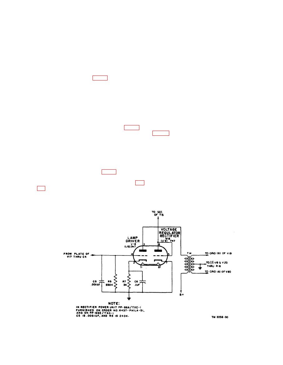
the grid (pin 4) of the lamp driver triode section
no output. Output transformer T15 has two
(pins 2, 3, and 4) of V18.
secondaries: one feeding the exciter lamp, and the
other driving control voltage amplifier stage V21.
4) of the lamp driver section (pins 2, 3, and 4) of
lamp, which draws approximately 2.75 amperes of
V18, type 7N7, is driven by the voltage from V17,
which is applied across grid resistor R5. Capaci-
current. It has an incandescent filament which
tor C5 serves as a high-frequency suppressor.
emits steady light because of its well-regulated
supply voltage. While 1,800-cycle voltage is ap-
This section of V18 is biased by the flow of plate
plied, thermal inertia of the heavy filament is high
current through cathode resistor R7, which is by-
and a 3,600-cycle light ripple is present but does
passed by C6. The primary of transformer T14
not affect operation in any way.
is the plate load.
f. Control Voltage Amplifier (V21 and V23)
Secondary No. 1 of transformer T15 and pins 5,
tion of V21, 7L7 (the control voltage amplifier)
6, and 7 of V18, form a dc rectifier for control
voltage amplifier V21. Plate and grid of this
is applied to the cathode through filter dropping
resistor R8 and gaseous voltage regulator tube
section of V18 are tied together and form a diode
V23 (type R1160A or 1B47 in unlettered models,
used as a half-wave rectifier on the 1,800-cycle
type 5651 in later models). The plate of V21
signal. The grounded cathode is the positive
is positive with respect to the cathode because it
terminal of this power supply. Capacitor C9 is
is connected to ground, the positive side of the
across secondary No. 1 of T15 (fig. 70) to suppress
voltage source, through plate resistor R11. Re-
high peak voltages.
sistor R12 is the screen resistor. A voltage-
dividing network in the grid circuit is composed of
resistors R9, R15, and R14. Resistor R15 is
of driver transformer T14 drives the grids of push-
variable to provide adjustment of the regulated
pull class AB1 tubes V19 and V20, which are C57
output voltage. Any variations in the voltage are
tubes. This is a power output stage biased by


