crease is developed across R9 and the portion of
amplified by tube V21, and applied through
R15 and is applied as positive bias to the grid of
resistor R10 directly to the grid of first lamp
V21. The reference voltage across V23 remains
amplifier V17. If the lamp output voltage
constant. Tube V21 becomes more conductive,
becomes higher than normal, the output at
the drop across plate load resistor R11 increases,
secondary No. 1 of T15 will increase, and the
and the bias applied to the control grid of V17
rectified supply voltage for stage V21 will in-
becomes more negative. This reduces ampli-
crease. The bias on V21 is the voltage developed
fication of stage V17 and brings the output voltage
between cathode and grid, across V23, resistor
down to normal. In Rectifier Power Unit PP-
R9, and that portion of R15 between R9 and the
86/TXC-1, tube V23, type R1160 or 1B47, now
slider on R15. However, the voltage across
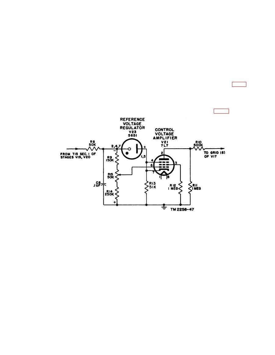
is obsolete and is replaced by type 5651 (fig. 72).
V23 (about 70 volts) is opposite to that across
In Rectifier Power Units PP-86A/TXC-1, PP-
the resistors. Consequently, the true bias on
86B/TXC-1, and PP-86E/TXC-1 tube V23 is
V21 is the difference between the voltage de-
type 5651, which requires a different value of R13
veloped across V23 and that developed across R9
to provide minimum stabilization current for the
and a portion of R15. When the supply voltage
tube and a different value of R9 (fig. 72).
increases, approximately 70 percent of the in-
Figure 72.
Control voltage amplifier, exciter lamp power supply, rectifier power units PP-86A/TXC-1, PP-86B/TXC-1,
and PP-86E/TXC-1.
107


