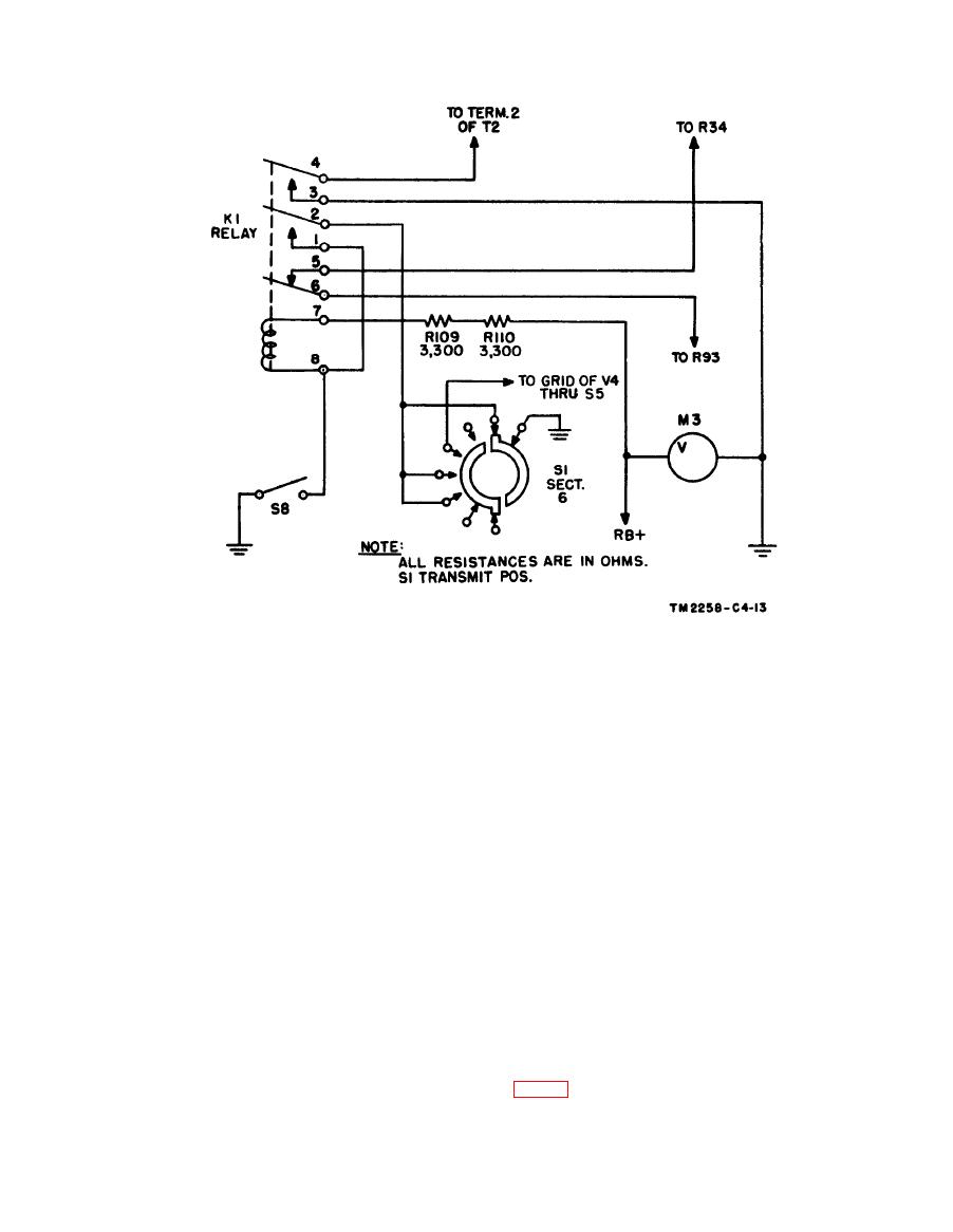
end of its travel, limit switch S8 closes. This
energizes relay K1. Contacts 5 and 6 open and
The phasing operation is performed jointly by
break the tuning fork signal to the grid of the
the transmitting and receiving operator. The
motor amplifier tube (V4). Contacts 3 and 4
transmitting operator turns the selector switch
close and short the output signal to ground.
of the transmitting transceiver to TRANSMIT
Contacts 1 and 2 close to keep the relay energized
and causes the scanning system to scan the
if the drum is moved away from the limit switch.
phasing ring on the scanning drum. A pulse,
b. To de-energize relay K1 before the next
in the form of an abrupt increase or an abrupt
transmission, the selector switch must be turned
decrease in the amplitude of the 1,800-cycle
to SET RANGE or STANDBY and the drum
carrier signal, is generated by the transmitter
moved to the right away from limit switch S8.
each time it scans the white spot on the dark
The relay coil is de-energized in these positions
phasing ring (once each second). The transmit-
since the path to ground from pin 2 of the relay is
ting operator does not operate the phasing switch
opened.
on his machine. The receiving operator phases
his machine to the transmitting machine by
c. When the transceiver is operated in the
turning the selector switch to RECORD PHOTO
RECORD PHOTO or RECORD DIRECT posi-
and by pressing the PHASE button. (In Fac-
tion, the automatic stop circuit functions in the
simile
Transceivers
TT-1D/TXC-1,
TT-1E/
same manner. The synchronous drive motor is
TXC-1, and TT-1F/TXC-1, the operator phases
stopped and the signal to record output amplifier
his machine to the transmitting machine by press-
V14 is shorted to ground. To de-energize the
ing the START PHASE switch toward PHASE.)
relay for the next recording, the selector switch
is turned to STANDBY and the drum is moved
to the right to disengage it from limit switch S8.


