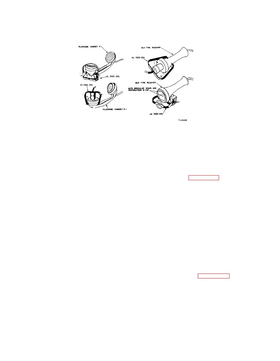
UC coupling coil attached to telephone headsets.
form of inconsistent lineweights throughout the
be transmitted over regular very-high-frequency
Copy.
(vhf) or ultra-high-frequency (uhf) fm radio cir-
cuits by merely connecting Facsimile Transceiver
(1) For hf transmission (below 40 mc), the
TT-1(*)/TXC-1 to the input and output termi-
effects of fading must be taken into con-
nals of the radio equipment. The received signals
sideration. If transmission is by ground
must be of sufficient strength to keep the limiter
wave only, over short distances, circuits
circuits of the fm receiver saturated at all times.
can be established for satisfactory re-
Details for this type connection using Converter
production of both photographic and
CV-2C/TX are given in paragraph 60.
black and white copy by utilization of
c. Frequency-Shift Transmission. To eliminate
suitable transmitting power levels. The
the effects of signal fading and to reduce the effects
channel bandwidth must be sufficient to
of interference and noise, a frequency-shift circuit
pass the full frequency range (both upper
using a regular cw transmitter is used. In this
and lower sidebands, 900 to 2,700 cps)
system, the amplitude variations of the facsimile
produced by the facsimile transceiver.
signals are converted into frequency variations,
(2) When transmission is by both ground and
and the facsimile signal components are trans-
sky wave, the effects of fading must
mitted over a regular cw radio channel as propor-
again be taken into consideration. Trans-
tional shifts in frequency rather than changes in
mitted picture elements arriving at the
amplitude. At the receiver, a crystal-controlled
receiving station, via the ground wave,
oscillator is heterodyned with the incoming fre-
may be out of phase with the same
quency-shift signals to produce corresponding af
picture element arriving via the sky
variations, and an af discriminator is used to
wave. This causes a change in the in-
convert the signal into the amplitude variations
stantaneous signal level and consequent
required for operation of Facsimile Transceiver
deterioration of the received copy.
TT-1(*)/TXC-1. Details for this type connec-
(3) Compensation may be made to reduce
tion using Converter CV-2C/TX and Exciter
the effects of fading by reducing the
Unit O-5B/FR are given in paragraph 61.
speed of transmission. Facilities for
half-speed operation are provided on
Facsimile Transceivers TT-1D/TXC-1,
When Facsimile Transceiver TT-1(*)/TXC-1
TT-1E/TXC-1, and TT-1F/TXC-1 by
is to operate in a conventional am radio transmit-
reducing the speed of rotation of the
ting and receiving circuit (SCAM), make connec-
scanning drum from 60 rpm to 30 rpm.
tions as follows:
b. Subcarrier Frequency Modulation (SCFM).
a. Plug one end of Cord CD-1018 into the
Both photographic and black and white copy can
transceiver RADIO RCVR jack (J2). Plug the


