input transformer T7. The center bind-
ing post, marked REC C T (fig. 168),
connects directly to the center tap of the
primary of T7 at all times. When the
selector switch is in TRANSMIT posi-
tion, and the DB METER indication is
+2 decibels (db), the two outside LINE
binding posts are connected through 300-
ohm resistors from secondary No. 2 of
output transformer T2. They will fur-
nish the standard 0 decibel referred to 1
milliwatt in 600 ohms (dbm) signal (.78
volt to a 600-ohm load) for connection
to commercial wire lines.
CARBON MIKE jack (J4). This is a
(4)
three-circuit jack. It is an output con-
nection that receives a type PJ-068 plug,
commonly furnished with carbon micro-
phones and is connected to one-half of
secondary No. 2 of output transformer
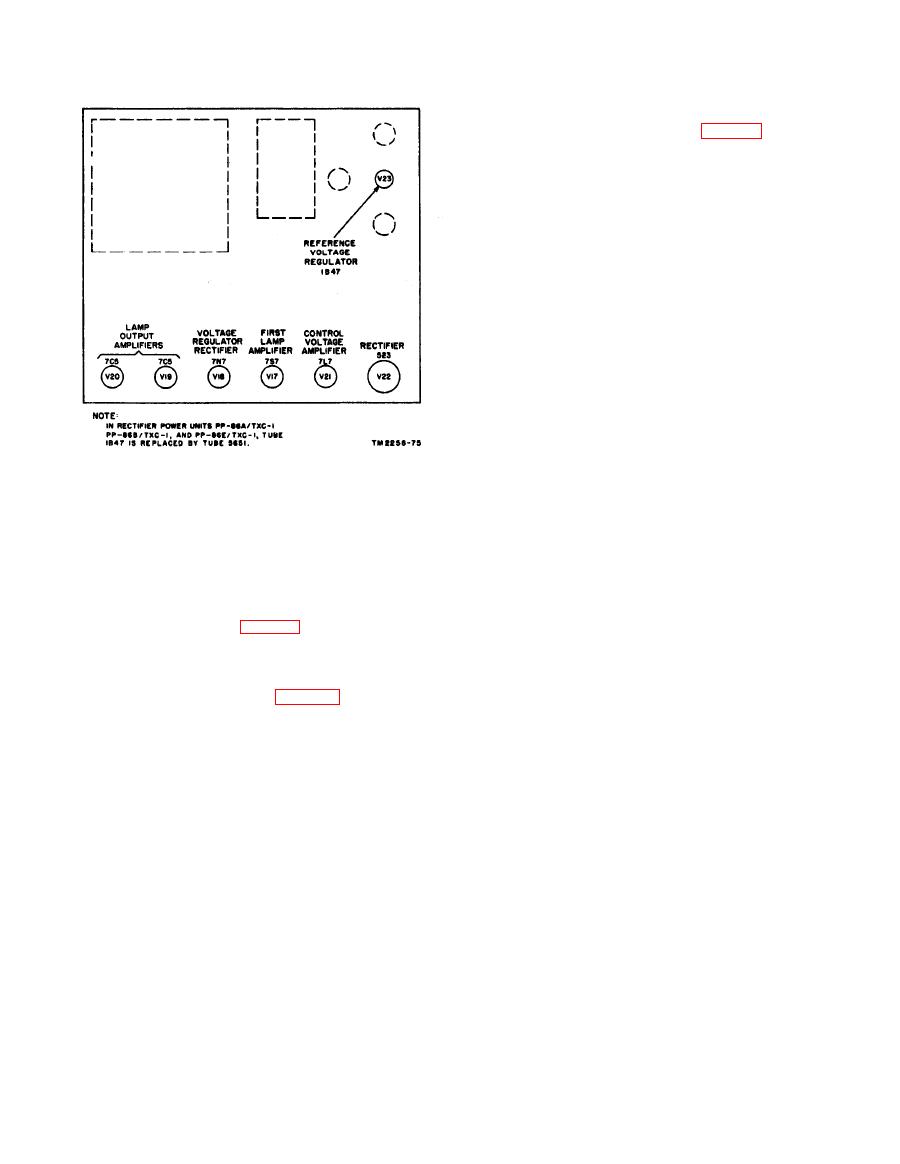
Figure 10. Location of tubes, rectifier power unit
T2. When the selector switch is on
PP-86(*)/TXC-1.
TRANSMIT, secondary No. 2 of trans-
(3) Connect the ac plug on the exhaust
former T2 is connected to the LINE
blower power cord to the 115-volt,
binding posts.
3-ampere outlet on the chassis of the
RADIO XMTR jack (J3). This is a jack
(5)
rectifier power unit.
connected in parallel with the CARBON
Caution: When replacing fuses, make sure
MIKE jack. It is used as a transceiver
not to use them in a circuit with a current
output, connection to the radio transmit-
rating above the specified value of the fuse.
ting circuit. The output level is .4 volt
into a 100-ohm load.
panel located on the right end of the facsimile
LINE JACK (J5). This two-circuit po-
(6)
transceiver is used for connecting the facsimile
larized jack requires a special plug. It
equipment to the communication circuit.
serves as the high-level input and output
connector for the transceiver. The
This is a two-circuit jack that receives a
polarized plug of the UC coupling coil
type PJ-055B plug. It is connected
fits this jack. When the selector switch
through a resistor attenuation network
is set at TRANSMIT, the LINE JACK
to the primary of T7, the audio-frequency
is connected across secondary No. 1 of
(af) input matching transformer (1:1
output transformer T2, and provides an
ratio) used for coupling between the line
output of 15.15 volts into a 600-ohm line
and the transceiver. It may be used for
(+26 dbm). One side of the LINE
monitoring the line.
JACK, labeled GND, is always at ground
(2) RADIO RCVR jack (J2). This is a two-
potential and is connected to the trans-
circuit jack wired in parallel with the
ceiver frame. When the selector switch is
PHONES jack, and may be used with a
set at RECORD PHOTO or RECORD
type PJ-055B plug as an input connec-
DIRECT, the LINE JACK is con-
tion to the transceiver.
nected to the secondary of transceiver
(3) LINE binding posts. These posts serve
input transformer T7.
as input and output connections for the
MOTOR JACK (J6). This three-circuit
(7)
transceiver. When the selector switch is
jack receives a type plug that permits
in either the RECORD PHOTO or
breaking into the 1,800-cycle signal cir-
RECORD DIRECT position, the LINE
cuit, between the motor amplifier buffer
posts are connected to the primary of
stage of the fork oscillator unit and the


