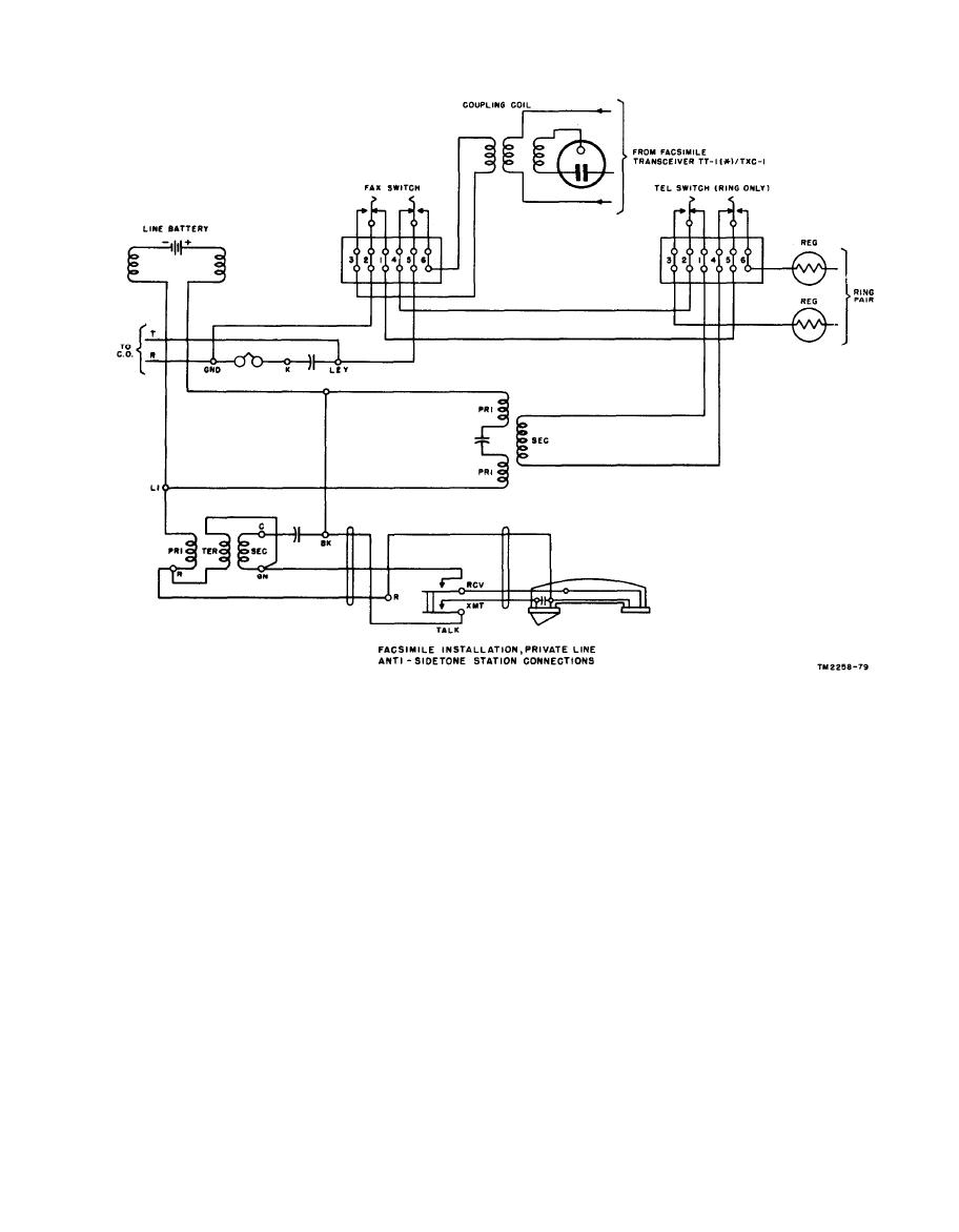
Facsimile installation, private line antisidetone station connectors.
when using Facsimile Transceiver TT-1/TXC-1,
the magnetic coupling connector on the UC
external telephones must be used at each end of
coupling coil, connect the telephone line directly
the circuit. Facsimile operation is also possible
to the 1V connector on the coupling coil. If the
over blind circuits, on prearranged schedules,
circuit loss is exceptionally high, the connector
without voice communication.
marked 6V on the coupling coil may be used,
provided, the line loss is at least 18 dbm before
reaching the first telephone exchange or repeater.
a. Subcarrier Amplitude Modulation (SCAM).
Warning: Do not use the coupling coil outputs
The average amplitude variations of the facsimile
marked 1V or 6V with any commercial or com-
signal change in proportion to the average densi-
mon battery circuits, or any circuit that uses sig-
ties of the picture being scanned. Slight ampli-
naling or ringing.
tude variations in the received signal, other than
those caused by the components of the facsimile
signal, also will cause objectionable distortion in
Facsimile Transceivers TT-1A/TXC-1 through
the received copy. This is especially noticeable
TT-1F/TXC-1 have built-in talk-back circuit
when receiving photographic material. When
facilities and permit communication between
transmitting black and white copy only, consider-
transmitting and receiving operators over the
able changes in amplitude can be tolerated, al-
same circuit used for facsimile signals. This
though distortion, caused by amplitude varia-
facility is controlled by the STANDBY-MON-
TALK switch (S5) on the front panel. However,
tions in the received signal, will appear in the


