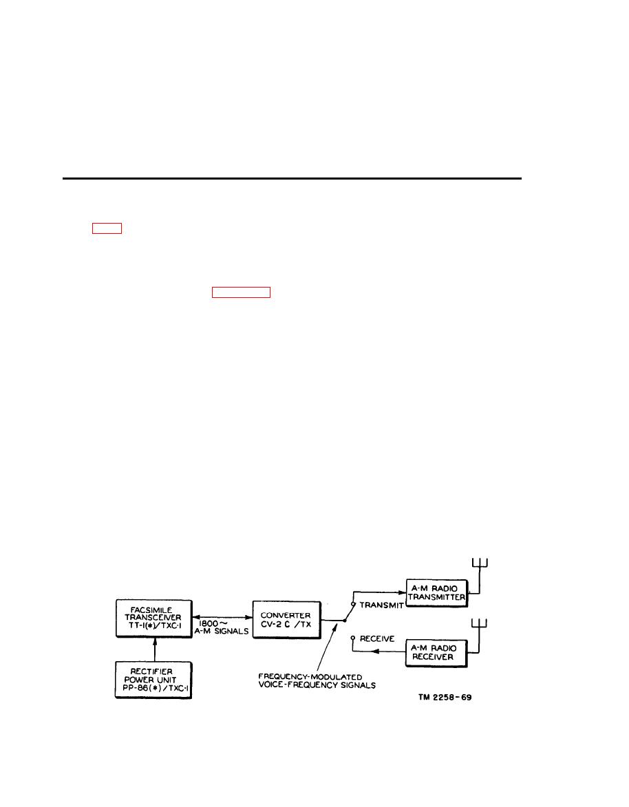
Section I. CONVERTER CV-2C/TX
60. Application
a. Connections. Locate Facsimile Transceiver
TT-1(*)/TXC-1 and Converter CV-2C/TX so
Converter CV-2C/TX is an electronic device
that the front panel controls of both units can be
which is used between the facsimile transceiver
operated easily. The tuning eye on the front
and the radio circuit in transmission and reception
of facsimile signals by the subcarrier frequency
panel of the converter must be in view.
modulation (SCFM) method. Figure 27 is a
(1) Normal operation.
block diagram that shows Converter CV-2C/TX
(a) Insert the input cord of Converter
CV-2C/TX into the LINE jack on the
connected in an am SCFM application. When
right-hand end of Facsimile Transcei-
transmitting, the converter changes 1,800-cps am
ver TT-1(*)/TXC-1.
signals from the facsimile transceiver into fre-
(b) Insert the connector plug of the ac
quency-modulated voice-frequency signals which
power cord into the socket (PS1) on
modulate a conventional radiotelephone trans-
mitter. The transmitted signal consists of a rf
the rear panel of the converter.
carrier on which is superimposed a constant level
(c) Insert the plug on the other end of the
ac cord into a 115-volt, 60-cps, ac
af modulation. The frequency of the af modula-
source.
tion is varied in accordance with the facsimile
(d) Insert one end of Cord CD1019 into
signals. When receiving, the radio signal is picked
Up by a conventional am communication receiver.
the RADIO XMTR jack on the front
The receiver output, which is fed into the con-
panel of the converter and the other
verter, consists of voice-frequency signals. The
end to the carbon microphone input of
converter changes these signals into am signals,
the radio transmitter.
which are fed to the receiving facsimile transceiver.
(e) Strap the GND and adjacent LINE
This type of circuit is less affected by fading and
terminal on the terminal board at the
interference than transmissions using conventional
rear of the converter.
(f) Plug one end of Cord CD-1018 into the
am. Complete information on Converter CV-
2C/TX is contained in TM 11-2252A.
RADIO REC. jack (J5) on the front


