TM 11-5820-803-12
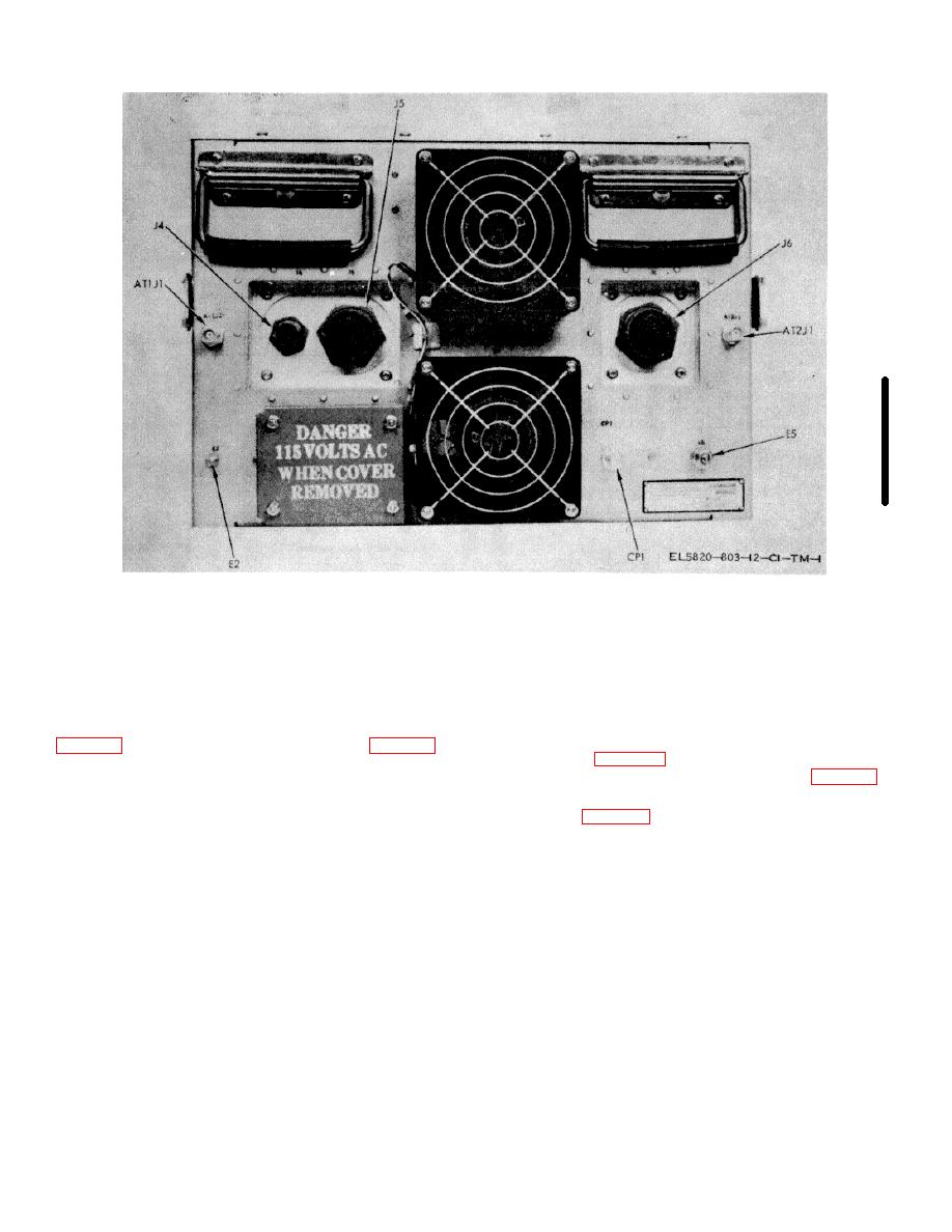
Figure 2-20. PSK modem, rear view.
to -55 dBm range (position 2).
file locations and reference designations. The reference
designations of the plug-in cards are marked on the card
(1) AN/MSG-46.
files next to each card location. Remove the PSK
(2) AN/TSC-54.
modem top and bottom covers, and set the internal
(3) AN/MSC-60 (HT).
switches as specified in the following paragraphs.
(4) AN/MSC-61 (MT).
a. Set S1 on input filter card assembly A21A1A22
b. Set S1 on input interface card assembly
A2A2A2A4 (fig. 2-22) for normal polarity (position 1)
For installations where the PSK modem is located in or
unless otherwise directed by the digital user (para 2-8a).
near the following terminals, set the switch to the 0
Table 2-2. PSK Modem Interconnections (fig. 2-20).
Reference designation
Title
Mating connector
AT1J1
70 MHz output
TNC coaxial plug
AT2J1
70 MHz input
TNC coaxial plug
J4
AC power
(cable supplied)
0
MS3126E24-61P with Glenier 90 Qwik-
J5
Site interface
TY GTR20S24B (SM-A-7313582)
J6
Coder/decoder interface
MS3126E24-61PW with Glenier 90O
Qwik-TY GTR20S24B (SM-A-731358-
2)
CP1
LOS Input
BNC coaxial
E2
Chassis ground
Terminal lug
E5
Signal ground
Terminal lug
2-21


