TM 11-5820-803-12
Section IV. INSTALLATION INSTRUCTIONS
the retaining catches on the rack section of the slides
2-16.
Tools, Test Equipment,
and
Materials
and push modem into cabinet. If a cable retractor is to
Required for Installation.
be installed, it is recommended that a Jonathan CRS-25
(SM-A571570-1) type be used.
The electrical
Tools required for installation of PSK modem are
connections are given in paragraph 2-19.
When
contained in Tool Kit, Electronic Equipment T]10/G (SC
dressing the cables, care should be taken to ensure
518091-CL-07). No test equipment or materials are
adequate length for pivoting the modem a full 90 degrees
required, other than the test equipment required by
in both directions from the normal position.
higher category of maintenance personnel for installation
checkout and the Tektronix 485A oscilloscope required
2-18. Special Installation
for circuit lineup.
Certain installations may require mounting of the PSK
modem so that the front panel of the unit protrudes from
2-17.
Installation Instructions.
the front of the rack. This installation is either to ensure
CAUTION
air flow through the modem cooling air inlets (fig. 2-18),
To minimize possibility of personnel
or is the result of installation in a shallow rack. This type
injury or equipment damage, two men
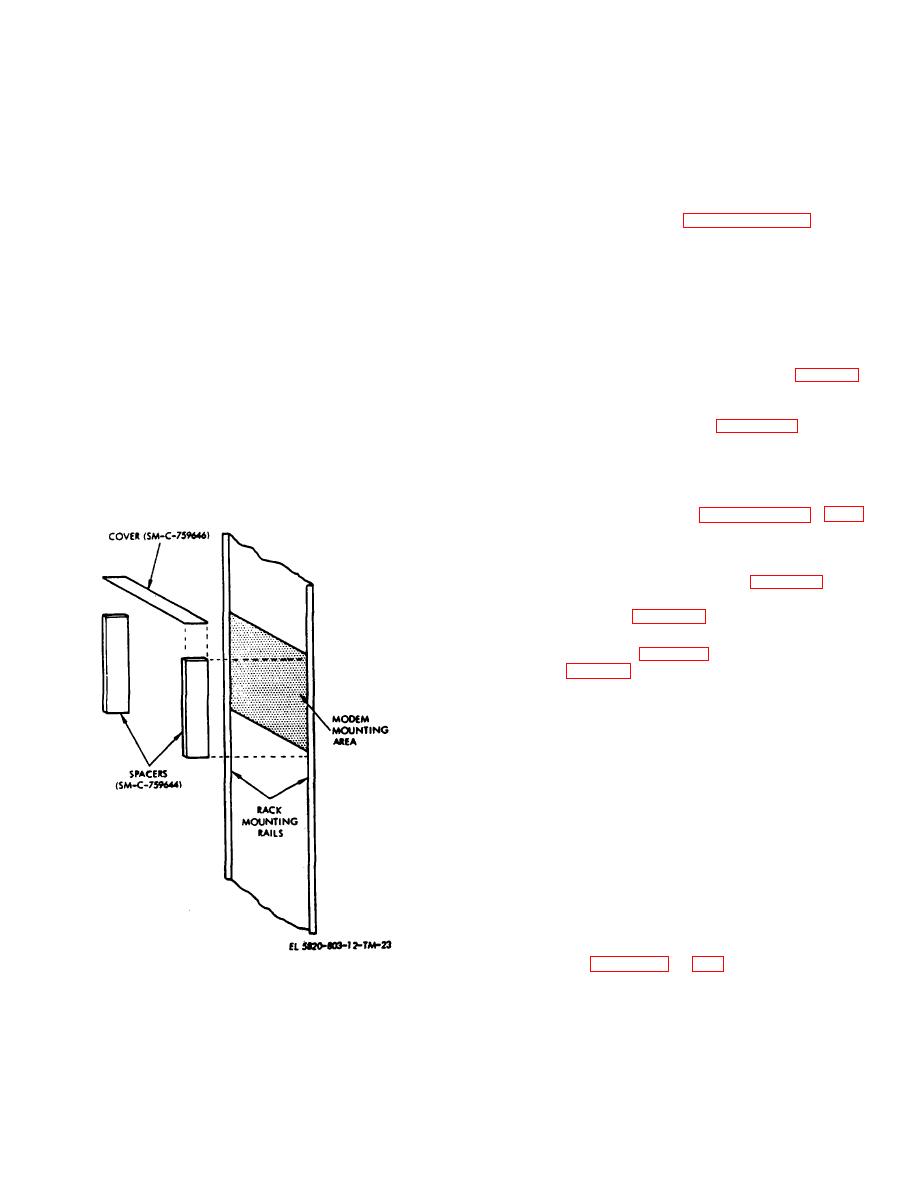
of installation differs from normal only in that two
are required to install or remove the
Spacers and a cover, illustrated in figure 2-19, must first
modem from the rack.
be attached to the rack.
The PSK modem is shipped with the chassis half of
2-19. External Connections
Jonathan 110 QDP-22-1 (SM-A-571569-2) slides The
a. When the PSK modem has been mounted in the
mating slide sections must be mounted in the rack prior
equipment rack as described in paragraph 2-17 or 2-18,
to modem installation. To install the modem, depress
it must be interconnected into the system This involves
connecting input ac power, ground, site interface, coder
interface, and 70 MHz input and output connections at
the rear panel of the PSK modem (fig. 2-20). The
reference designations and title of each interface
connector are listed in table 2-2.
b. The site and coder interface, J5 and J6, are
multi-conductor cables Table 2-3 lists the signals carried
by J5 while table 2-4 provides similar information for J&
Connections to ground terminals (E2 and E5) depend on
the site. If separate chassis and signal ground buses are
provided in the rack, point-to-point connections should
be made between the terminals and the respective
buses Connection of the signal ground (ES) is optional In
all cases, the chassis ground terminal should be
connected to the site ground system as a safety
precaution.
2-20. Switch and Internal Control Settings
The internal switches are located on selected plug-in
card assemblies in the PSK modem. The switches are
screwdriver-operated and have either two or three switch
positions. It is necessary to remove and reinstall two of
the plug-in card assemblies to set the switches, but most
of the switches may be operated without removing the
cards. Refer to figures 1-3 and 1-4 to determine card
Figure 2-19. Special installation accessories.
2-20


