TM 11-5820-803-12
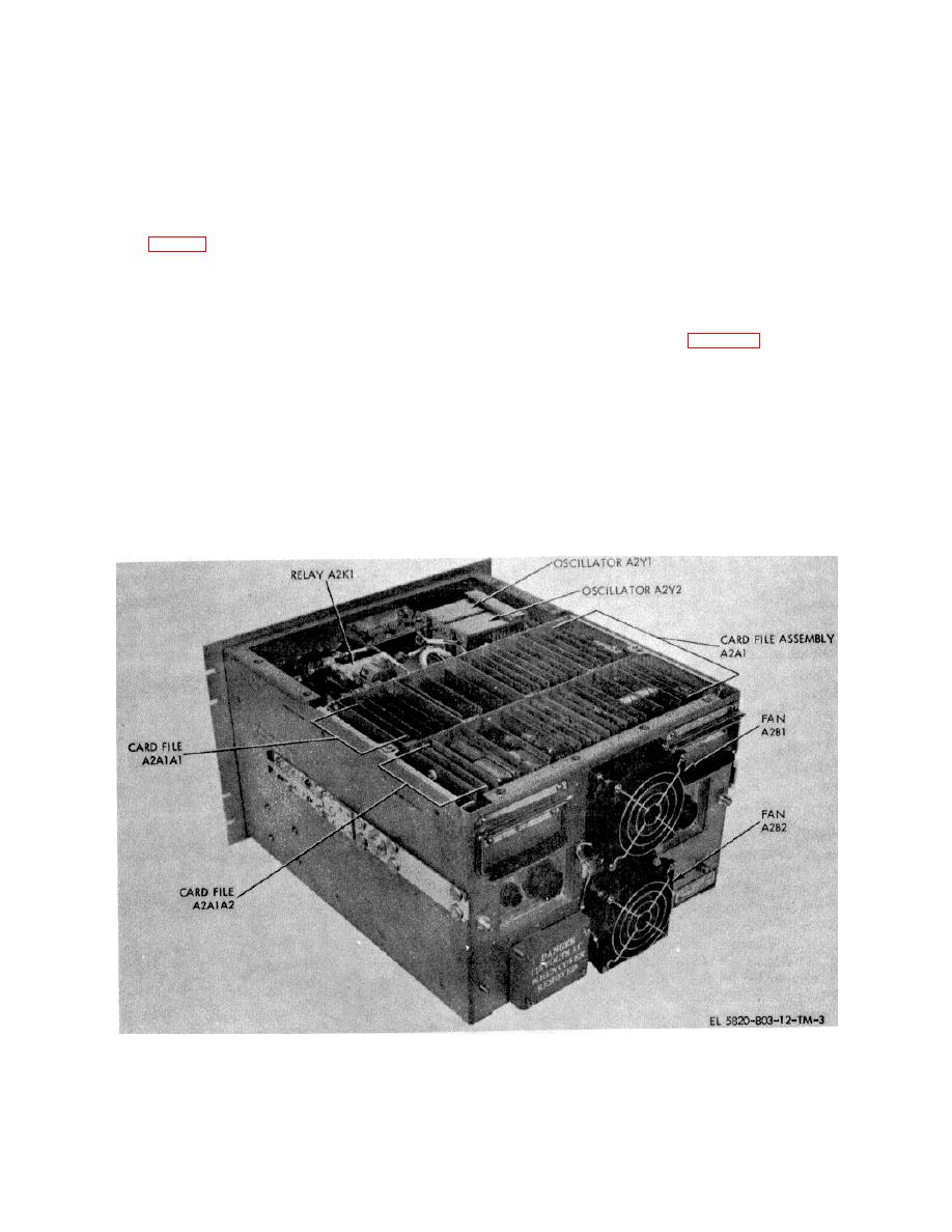
the A1 file and 9 cards in the A2 file. Located on the top
c. Data Rates.
The modem is capable of
section of the chassis forward of the card file are the
processing any data rate between 19.200 kb/s and
oscillator assemblies A2Y1, A2Y2, and the coaxial relay,
9.9999 Mb/s if no error-correcting coding is used. If
A2K1. The power supply, A2PS1, is located on the
internal external error correcting coding is used, the data
bottom section of the chassis forward of the card file.
rates are between 19.200 kb/s and 5.0000 Mb/s.
Transmit and receive section data rates are
1-8. System Application
independently selectable.
A variety of system configurations are possible using the
PSK Modem (fig. 1-5). The major options are listed in a
d. Digital User Interfaces. The interface between
through d below.
the PSK Modem (usually located in or near the earth
terminal) and the digital user may be accomplished in
a. Earth Terminals.
The modulated 70 MHz
several ways as listed below. For detailed information on
interface signals are compatible with various equipment
applications and interface requirements, refer to the
including the following:
system planning section of chapter 2.
(1) AN/MSC-46.
(1) Direct interface with a nearby digital user
(2) AN/TSC-54.
via the MIL-STD-188 inputs and outputs of the modem.
(3) AN/MSC-60 (HT).
(2) Interface with a remotely located digital
(4) AN/MSC-61 (MT).
user via 50Ω or 75Ω coaxial cable, or 75 Ω balanced
b. Error-Correcting Coders/Decoders. The modem
cable. This type of interface requires a Modem, Digital
operates in the following error-correcting coding and
Data MD-920/G (ICF modem (TM 11-5820-804-12)) at
decoding modes:
the digital user end of the cable.
(1) No coding.
(3) Interface with a remotely located digital
(2) Internal moderate gain coder/decoder.
user via a line-of-sight (LOS) microwave link. This type
(3) External high gain coder/decoder.
of interface also requires an ICF Modem at the digital
user end of the link.
Figure 1-3. PSK modem viewed from top rear (top cover removed).
1-3


