TM 11-5820-803-12
POSITION 1 -SELECTS +23 dBm 3 dB OUTPUT
amplifier. Adjust the F equalization by turning R12 (and
POWER LEVEL AT CABLE DRIVER
adjust R10 equally if the 75 ohm balanced input is used)
OUTPUTS AND +1 dBm 3 dB OUTPUT
counterclockwise until a signal similar to B, figure 2-28 is
POWER LEVEL AT LOS MICROWAVE
observed. Because the amplitude will decrease, it may
DRIVER OUTPUT.
be necessary to increase the oscilloscope gain to
observe this adjustment. Then adjust R2 to obtain an
POSITION 2 - SELECTS +10 dBm :3 dB OUTPUT
amplitude of 2.4 V p-p. Monitor TP2 and, if necessary,
POWER LEVEL AT CABLE DRIVER
readjust R2 to obtain an amplitude of 1.2 V p-p.
OUTPUTS AND -12 dBm +3 dB OUTPUT
(4) For a long cable input, use an oscilloscope
POWER LEVEL AT LOS MICROWAVE
to monitor TP1 on the LOS/cable receiver and decoder
DRIVER OUTPUT.
card (A2A2A2A1). If the amplitude is less than 2.4 V p-
p, adjust R2 to obtain an amplitude of 2.4 V pp. If the
POSITION 3 -SELECTS 0 dBm 43 dB OUTPUT
amplitude is greater than 2.4 V pp, proceed even if the
POWER LEVEL AT CABLE DRIVER
signal obviously causes saturation of the amplifier.
OUTPUTS AND -22 :3 dB OUTPUT
Adjust the first stage of equalization by turning R12 (and
POWER LEVEL AT LOS MICROWAVE
adjust R10 equally if the 75 ohm balanced input is used)
DRIVER OUTPUT.
counterclockwise until a signal similar to A, figure 2-28 is
observed. Because the amplitude will decrease, it may
be necessary to increase the oscilloscope gain to
observe this adjustment. Then, adjust R2 to provide the
maximum amplitude obtainable without causing
saturation of the amplifier. Monitor TP2 and adjust the
Figure 2-25. LOS/cable driver output level selection S1
second stage of equalization by turning R14
(viewed from top of LOS/cable driver, card, SM-D-
counterclockwise until either a waveform similar to B,
74F081, A2A2A2A3).
operating rate. Coordinate with the remote ICF modem
site to obtain a 5.0000 Mb/s data input.
b. Set all variable resistors (R2, R10, R12, R14) en
on the LOS/cable receiver and decoder card fully
clockwise.
c. Adjust oscilloscope sweep rate to 100 nsec/cm
and perform one of the following alinements, depending
on the site configuration:
(1) For an LOS input, use an oscilloscope to
monitor TP1 on the LOS/cable receiver and decoder
card (A2A2A2A1) and adjust R2 for an amplitude of 2.4
V p-p. Then monitor TP2 and, if necessary, readjust R2
for an amplitude of 1.2 V pp.
(2) For a short cable input, use an
oscilloscope to monitor TP1 on the LOS/cable receiver
and decoder card (A2A2A2A1). If the amplitude is
greater than 2.0 V p-p, adjust R12 (and adjust R10
equally if the 75 ohm balanced input is used) to obtain an
amplitude of 2.0 V p-p. After this adjustment or if the
initial amplitude was less than or equal to 2.0 V p-p,
adjust R2 to obtain an amplitude of 2.4 V p-p. Then
monitor TP2 and readjust R2 if necessary to obtain an
amplitude of 1.2 V pp.
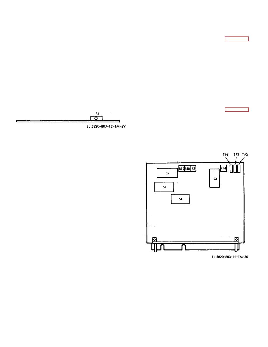
Figure 2-26. LOS/cable receiver and decoder selection
(3) For a midrange cable input, use an
switches S1 though S4 (viewed from component side of
oscilloscope to monitor TP1 on the LOS/cable receiver
LOS/cable receiver and decoder card, SM-D-742089,
and decoder card (A2A2A2A1). If the amplitude is less
A2A2A2A1).
than 2.4 V p-p, adjust R2 to obtain an amplitude of 2.4 V
p-p. If the amplitude is greater than 2.4 V p-p, proceed
even if the signal obviously causes saturation of the
2-25


