TM 11-5820-803-12
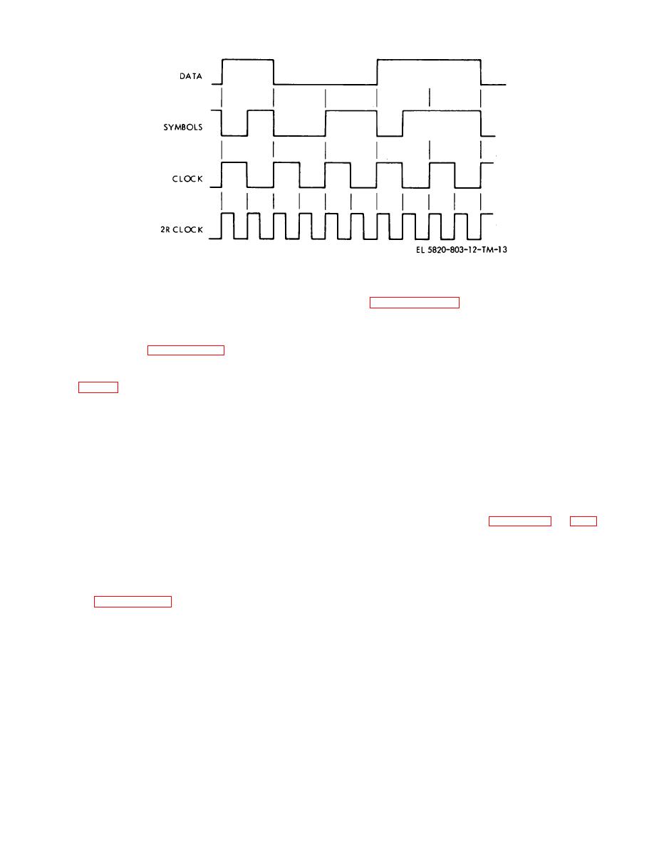
Figure 2-8. External coder/decoder interface phasing.
exception of the LOS input, are provided at the site
See paragraph 2-20c for further details of switch
interface connector, J5, on the rear panel of the modem.
settings.
The LOS input is a BNC type connector also located on
(1) The Internal clock output is derived from
the rear panel.
Further information on interface
an internal reference clock generator. This internally
connections is given in paragraph 2-19.
generated clock, which is equal in rate to the setting of
the INPUT DATA RATE switches 0.005%, is available
2-8.
Direct Digital Interface
to the digital user as an optional clock source.
(2) The standard data output is that data
When the PSK modem interfaces with a digital user
which is received and decoded by the PSK modem
located near the modem, a direct digital interface via
receiver.
balanced line drivers and receivers is employed. The
(3) The standard clock output is a clock
interface signals are listed in a and b below.
signal, which is synchronized with the standard data
output, and is internally regenerated by the PSK modem
a. Input Signals.
receiver.
(1) The standard data input accepts data from
(4) The alternate data and clock outputs are
the digital user for modulation, coding, and transmission
identical to the standard data and clock outputs.
over the communications link. The PSK modem is
The input and output characteristics of the data and
capable of synchronizing an internal clock to the data
clock signals are illustrated in figures 2-10 and 2-11. All
input for use in the coder and transmitter operation.
the input and output impedances are 75 ohms 10%.
(2) Use of the standard clock input is optional.
The following factors must be considered in planning the
The PSK modem may be configured to use this input
direct digital user interfaces:
clock to control modulation, coding, and transmission of
(a) The use of 75-ohm balanced
the standard data input signal. An internal switch in the
transmission
cable,
such
as
RG-108A/U
is
PSK modem provides the capability of inverting the clock
recommended (although not necessary for short runs).
signal. See paragraph 2-20b for further details on setting
(b) All direct digital outputs should be
of this switch.
terminated with 75-ohm loads. Unused outputs should
b. Output Signals. All direct digital outputs may be
be terminated at the PSK modem rear panel connector.
inverted by internal switches in the PSK modem.
(c) The length of cable which may be
driven is a function of the data rate, the phase distortion
of the cable used, and the loss of the cable type used.
2-10


