TM 11-5820-803-12
2-9.
ICF Interfaces
than 30 dB power loss at 5 MHz (regardless of the actual
data rate). The cable loss for installation must be
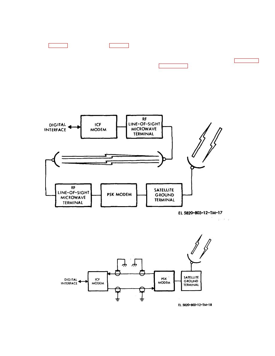
a. General.
The PSK modem is capable of
determined from the cable manufacturer's data and the
interfacing with the digital user over a line-of-sight (LOS)
cable length. For example, assume that RG-217/U cable
microwave link (fig. 2-12) or a shielded cable (fig. 2-13)
is being considered for a 10,000-foot installation. The
using an Interconnect Facility (ICF) modem located at
cable loss characteristic, in dB/100 feet, for RG-217/U
the digital user site. Both the PSK and ICF modems
cable (unbalanced type cable) is shown in figure 2-14.
contain identical LOS/cable driver circuits and LOS/cable
From figure 2-14, it can be seen that cable loss
receiver and decoder circuits. These circuits provide the
characteristics (a) at 5 MHz is 0.28 dB/100 feet
appropriate interface levels and code conversion to and
Therefore, for a cable length (L) of 10,000 feet of RG-
from the digital user's format to make the interface signal
217/U, the total cable loss can be determined from the
compatible with either transmission system
relationship:
b. Cable Installation.
cable loss = (al) 100.
(1) Cable selection. The cable selected for
cable loss = (0.28 x 10,000) 100 = 28 dB.
data transmission should normally provide no more
Since the cable loss in the example given above is less
than 30 dB, that length of RG-217/U would be usable
Figure 2-12. ICF/PSK modem configuration via line-of- sight (LOS) microwave terminal.
Figure 2-13. ICF/PSK modem configuration via shielded RF cable.
2-13


