TM 11-5805-424-15/NAVELEX 0967-220-9010/TO 31W2-2G-41
(1)Connect the oscilloscope between test point TP10 on
(d) If delay equalization cannot be
the control shelf (fig. 2-3) and ground, and adjust the
achieved without introducing distortion, operate the
oscilloscope to observe at least two eye-patterns.
EQUALIZER switch to OUT.
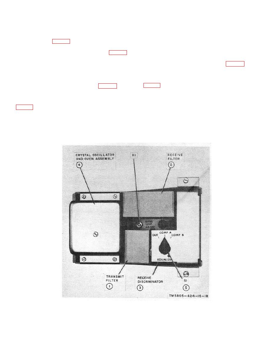
(2) Rotate the EQUALIZER switch (fig. 2-7)
(2) Adjustable.
to the position that provides a maximum opening of the
(a) Connect the oscilloscope between
eye-pattern; then, disconnect the oscilloscope.
test point TP10 on the control shelf (fig. 2-3) and
c. Delay Equalization (MX-7379/G).
ground, and adjust the oscilloscope to obtain at least two
eye-patterns.
(1) Selectable.
(b) Operate the EQUALIZER switch
(a) Connect the oscilloscope between
test point TP10 on the control shelf (fig. 2-3) and
ground, and adjust the oscilloscope to observe at least
(c) Adjust the EQ1 DELAY ADJ control
two eye-patterns.
to obtain a maximum opening in the eye-pattern without
distortion; note the pattern.
(b) Operate the EQUALIZER switch
(fig. 2-8) to COMP.
(d) Adjust the EQ2 DELAY ADJ control
to obtain a maximum opening in the eye-pattern without
(c) Operate the EQ1 and EQ2 FREQ
distortion; note the pattern.
switches to each of their positions, in various
combinations, until a maximum opening is obtained in
the eye-pattern without distortion.
Figure 2-7. Plug-in module of Modem Subassembly MX-7373/G, MX-7375/G, MX-7383/G, or MX-7385/G.
Change 5
2-10


