TM 11-5805-424-15/NAVELEX 0967-220-9010/TO 31W2-2G-41
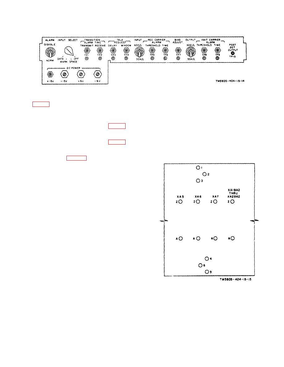
Figure 2-3. Control shelf, controls and test jacks.
(b) Strap terminals 1 and 2 on assembly
NOTE
A10 (D, fig. 2-5).
No frequency divider circuit card is
e. Synchronization or Common Alarm.
inserted in the A18A2-A29A2 slot
(1) Signal. To provide an external synchronize
when Modem subassembly MX-7384,
disable signal at terminal 20 of terminal board TB1,
or MX-7385, or MX-7386 is installed.
strap terminals 1 and 2 on assembly A12 (E, fig. 2-5).
When these subassemblies are used
(2) Common Alarm. To provide an external
a strap must be connected from pin
common alarm at terminal 20 of terminal board TB1,
19 to pin 20 of P1 of the module.
strap terminals 2 and 3 on assembly A12 (E, fig. 2-5).
(This is to bridge the circuit gap
f. Negative Mark Input.
Each MX-73(*)/G is
which results when the A18A2-A29A2
strapped to receive positive mark signal (terminals 13
slot is vacant.)
and 14 of connector P1, fig. 6-43, 6-44, or 6-45). If the
MD-674(P)/G is to be used to receive a negative mark
signal, remove the strap from terminals 13 and 14 of
connector P1 on the MX-73(*)/G and reconnect the strap
between terminals 14 and 15.
2-4.1. Coordination of Components
For operation at the various frequencies the
components to be installed are matched in accordance
with the following table, and paragraph 1-6.
Modem
Card
subassembly
determining divider
assembly
MX-7372/G ..............D80034200 (8) ............A18A2-A19A2
MX-7373/G ..............D80034200 (8) ............A18A2-A19A2
MX-7374/G ..............D80034190 (4) ............A20A2-A22A2
MX-7375/G ..............D80034190 (4) ............A20A2-A22A2
MX-7376/G ..............D80034190 (4) ............A20A2-A22A2
MX-7377/G ..............D80034180 (2) ............A23A2-A29A2
MX-7378/G ..............D80034180 (2) ............A23A2-A29A2
MX-7379/G ..............D80034180 (2) ............A23A2-A29A2
MX-7380/G ..............D80034180 (2) ............A23A2-A29A2
MX-7381/G ..............D80034180 (2) ............A23A2-A29A2
MX-7382/G ..............D80034180 (2) ............A23A2-A29A2
MX-7383/G ..............D80034180 (2) ............A23A2-A29A2
MX-7384/G ..............None.
MX-7385/G ..............None.
Figure 2-4. Harness card strap terminal locations.
MX-7386/G ..............None.
Change 5 2-4


