TM 11-5805-424-15/NAVELEX 0967-220-9010/TO 31W2-2G-41
(a) Strap terminals 1, 2, and 3 on
radiation. Be careful not to damage
assembly A3 (C, fig. 2-5).
the rfi gasket when securing the
chassis to the case.
f. Connect the cable connector on the rear of the
chassis; slide the chassis completely into the case, and
secure the chassis to the case with the front panel
securing screws.
2-4. Strapping Options
a. AC Power. Determine the type of alternating
current (ac) power to be used and be sure that only the
required strapping ((1) or (2) below) is used.
(1) 115 volts.
Connect a strap between
terminals 1 and 2, and terminals 3 and 4 on the ac
power input strapping terminal board (fig. 1-7).
(2) 230 volts.
Connect a strap between
terminals 2 and 3 of the ac power input strapping
terminal board (fig. 1-7).
b. Station Clock Signal.
(1) Internal. Strap terminals TP3 and TP4 on
assembly A1 (A, fig. 2-5).
(2) External. Strap terminals TP1 to TP2 and
TP4 to TP5 on assembly A1 (A, fig. 2-5).
c. Received Data Output Signal.
(1) Retimed.
(a) Strap terminals 1 and 3 on the
harness card (fig. 2-4).
(b) Strap terminals 3 and 4 on assembly
A11 (B, fig. 2-5).
(2) Not retimed.
(a) Strap terminals 2 and 3 on the
harness card (fig. 2-4).
(b) Strap terminals 2 and 4 on assembly
A11 (B, fig. 2-5).
d. Order Wire Signal. If the order-wire facility is to
be used, strap terminals 1 and 4 on assembly A11 (B,
(1) Terminal applications. The manual reset
option may be used at both MD-674(P)/G's in the link,
but only one of the MD-674(P)/G's may use the
automatic reset option
(a) Manual reset. Strap terminals 5 and 6
on the harness card (fig. 2-4).
(b) Automatic reset. Strap terminals 4
and 6 on the harness card (fig. 2-4).
(2) Repeater applications. Each MD-674(P)/G
may be strapped as described in (1) above when an
operator is stationed at the site. When no operator is
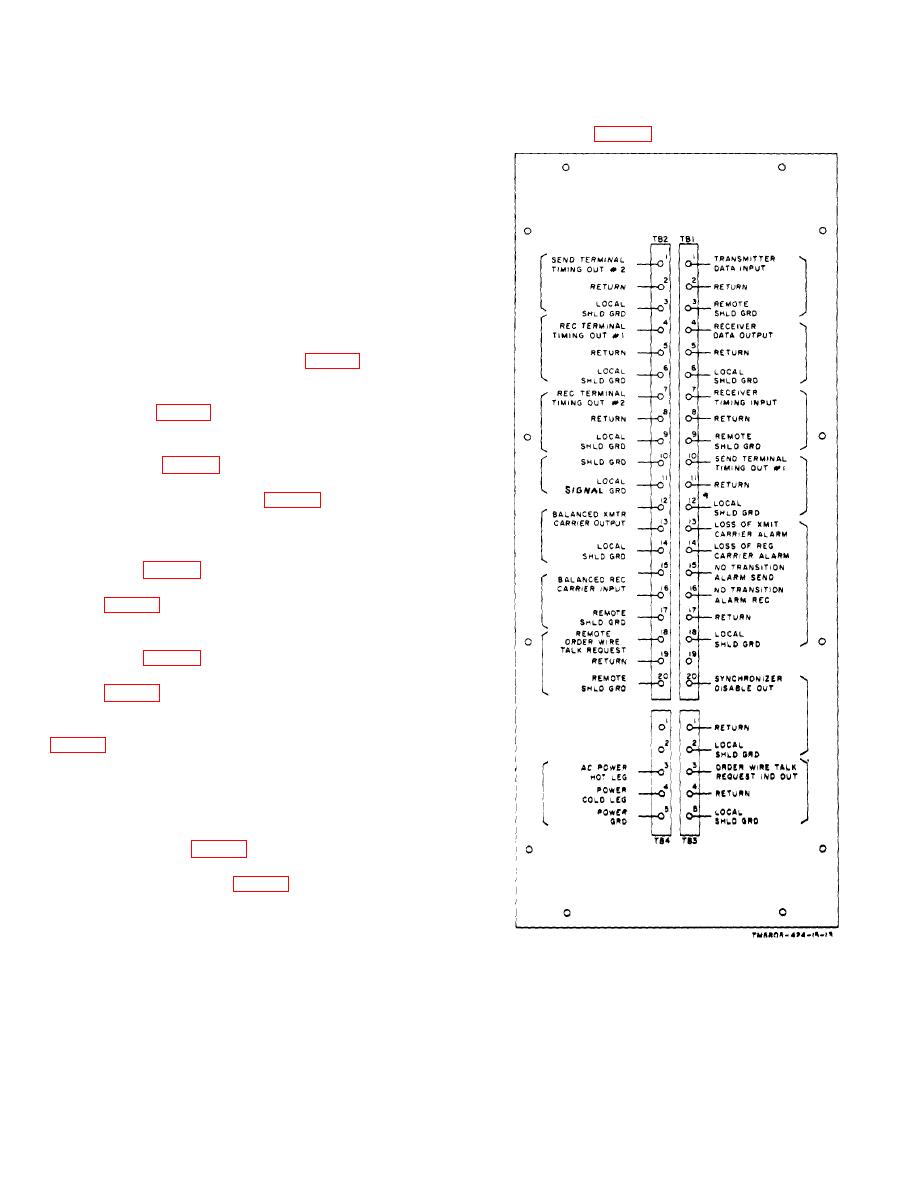
Figure 2-2. Terminal board identification diagram.
stationed at the site, make the strapping connections
indicated below.
Change 5 2-3


