TM 11-5805-424-15/NAVELEX 0967-220-9010/TO 31W2-2G-41
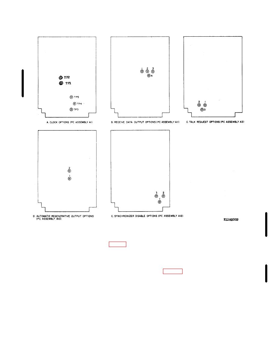
Figure 2-5. Printed-circuit card assembly strap terminal locations.
(3) Connect the uncorrected timing signal from
terminals 1,2,and 3 of terminal board TB2 to the
(1) Connect the 115- or 230-volt ac power to
digital data transmit equipment.
terminals 3,4, and 5 of terminal board TB4.
(2) Connect the digital input (to be transmitted to
Note. If security equipment is used
terminals 1, 2, and 3 of terminal board TB1.
timing signal from terminals 10, 11,
Note. The digital input return line
and 12 of terminal board TB1 to the
should be returned to a signal
security transmit equipment.
ground at the signal source end. If it
is not, connect the return line
(4) Connect the digital output (received) from
(terminal 2 of TB1) to the signal
terminals 4, 5, and 6 of terminal board TB1 to
ground at terminal 11 of terminal
the digital data receive equipment.
board TB2 of the MD-674(P)/G.
Change 5
2-5


