TM 11-5805-424-15/NAVELEX 0967-220-9010/TO 31W2-2G-41
CHAPTER 3
OPERATION AND OPERATOR'S MAINTENANCE
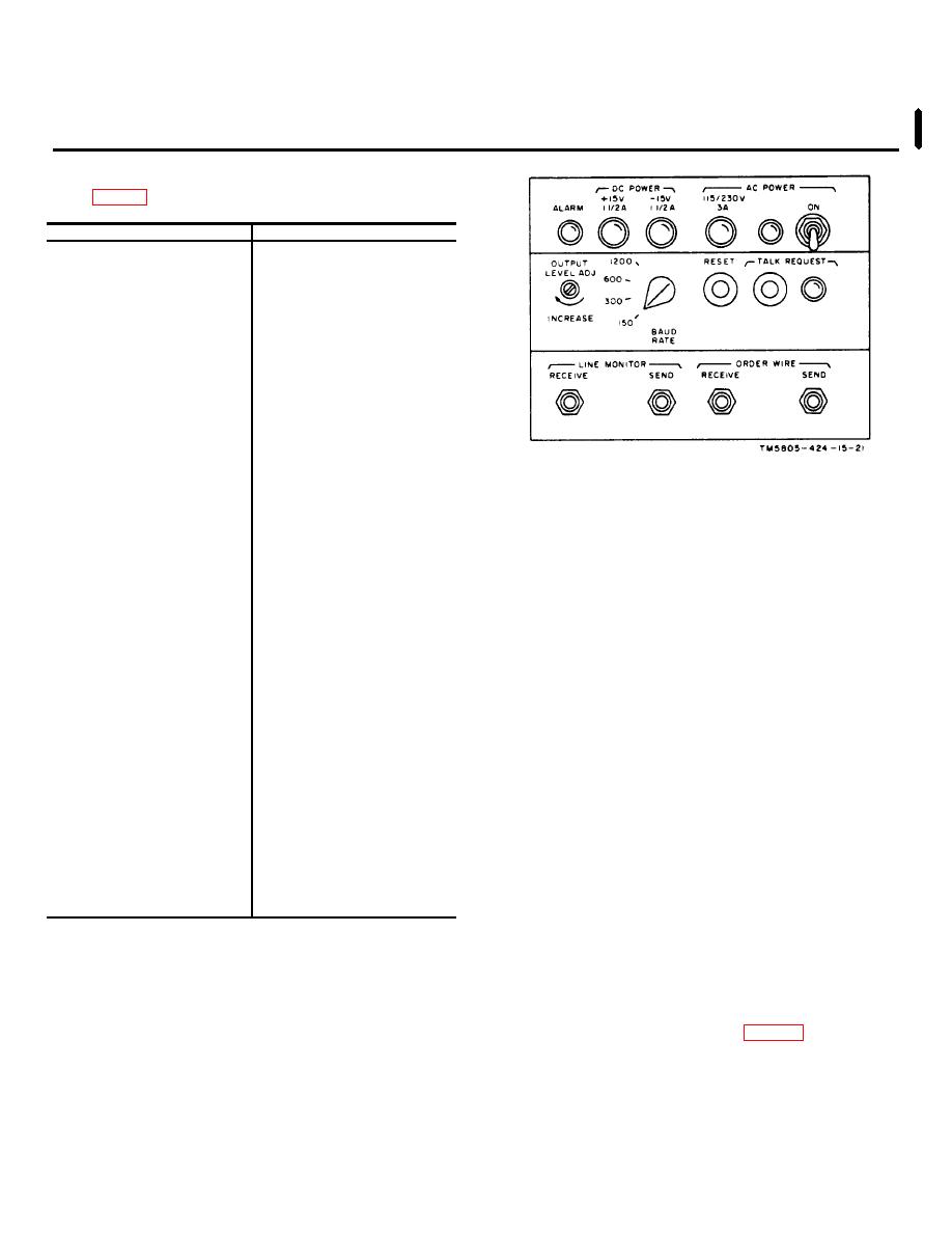
3-1. Controls, Jacks, and Indicators
Control, jack, or indicator
Function
ALARM indicator
Lights to indicate signal
failure.
DC POWER fuses:
+15V 11/2A
Lights when blown; pro-
tects +15-volt dc
power supply.
-15V 11/2A
Lights when blown; pro-
tects -15-volt dc
power supply.
AC POWER:
115/230V 3A fuse
Lights when blown; pro-
tects ac circuitry.
Indicator
Lights when ac power is
applied.
ON switch
Two-position:
Figure 3-1. Front panel controls and indicators.
ON-applies ac
power to unit.
3-2. Starting and Stopping Procedures
OFF (down)-removes
ac power from unit.
Caution: The OUTPUT LEVEL ADJ
BAUD RATE switch
Four-position: selects baud
control and the BAUD RATE switch
rate desired for asso-
are preset during installation and
ciated MX-73(*)/G.
TALK REQUEST
Resets order-wire circuits
initial adjustments. Do not change
RESET pushbutton.
for normal data operation.
settings of either control in an
TALK REQUEST:
operating system.
Changing the
Pushbutton
Activates order-wire request
setting of either control will interrupt
signal.
system service.
Indicator
Lights when order-wire
a. Starting.
request signal is received.
LINE MONITOR jacks:
(1) Set the BAUD RATE switch to the desired
RECEIVE
Allows external monitoring
BAUD RATE position.
of received vf signal.
SEND
Allows external monitoring
Note: The BAUD RATE switch may
of send vf signal.
be set to the baud rate that
ORDER WIRE jacks:
corresponds with the baud rate of
RECEIVE
Provides connection to
teletypewriter receive
the MK-73(*)/G installed or any lower
equipment.
multiple of the MX73(*)/G baud rate.
SEND
Provides connection from
(2) Operate the AC POWER switch to ON.
teletypewriter send
b. Stopping. Operate the AC POWER switch to
equipment.
the off (down) position.
3-3. Order-Wire Operation
a. Initiating Call.
(1) Plug the send cord of the teletypewriter into the
ORDER WIRE SEND jack (fig. 3-1).
(2) Plug the receive cord of the teletypewriter into
the ORDER WIRE RECEIVE jack.
Change 6
3-1


