TM 11-5820-803-12
Table 4-4. BER Test Control Settings.
Control
Position
ALARM RESET/OFF
OFF
TRANSMIT SOURCE
LINK
TRANSMIT ERROR CODING
Same as normal operational setting for RECEIVE ERROR CODING switch
INPUT DATA RATE
Same as normal operational setting of SYMBOL RATE switches if no error
coding is used; one-half the normal operational setting of the SYMBOL
RATE switches if error coding is used.
DIFF ENCODE
Normal operational setting (table 3-2)
DIFF REECHOED
Normal operational setting (table 3-2)
SYMBOL RATE '
Normal operational setting (table 3-2)
RECEIVE ERROR CODING
Normal operational setting (table 3-2)
METER
ERROR COUNT
error rate for each Eb/No, value is plotted on the
modem terminal interfaces (70 MHz input and output)
theoretical bit error rate performance graph (fig. 2-4).
must be disconnected from the terminal to conduct this
Actual performance must be within 1.8 dB of the
test. Weekly testing is recommended; however, the test
appropriate theoretical coding curve. The selected E/N,,
schedule may vary depending on the operational
values for the coding options are:
requirements at the site.
Coding
Eb/No, in dB
(2) To perform this test, a calibrated energy
per bit to noise density (El/N,) ratio must first be
Differential
3, 5, and 11.5
established (para 3-10d). The calibrated noisy signal
Internal
5, 7, and 8.5
required may be generated by using the Test Set,
External
3 and 5.5
Modem TS-3580( )/G. Bit error rate measurements are
then made (b below), using this noisy signal, to verify that
b. Bit Error Rate (BER) Measurement.
the modem is operating within tolerance.
(1) If modem is deenergized, perform the
(3) To provide a more comprehensive
preliminary starting procedure (para 3-4).
indication of the actual bit error rate performance of a
(2) Set the modem controls per table 4-4 and
PSK modem, bit error rate measurements are taken for
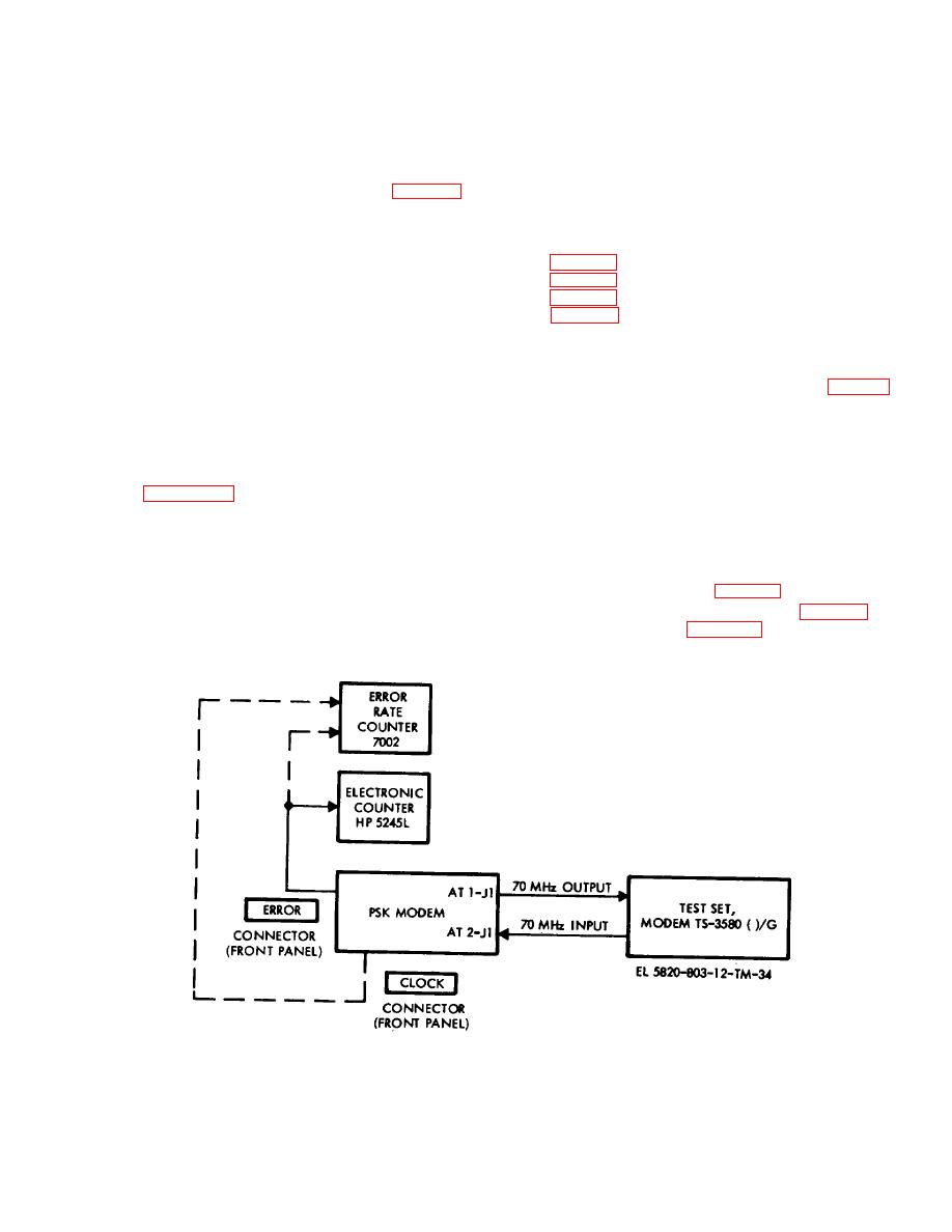
connect the equipment per figure 4-1.
several Eb/No, values. The selected E,/N,, con values
are based on the type of coding used. The measured bit
Figure 4-1. Bit error rate measurement, test setup.
4-3


