TM 11-5820-803-12
Table 5-3. Power Supply-measurements.
Voltage
Limits
Connector pin
+5V
+4.95 to +5.05V
A2A2A2A947
-6V
-4.95 to -5.05V
A2A2A2A9--4
+15V
+ 14.98 to + 15.02V
A2A2A2A9-13
- 15V
- 14.98 to -15.02V
A2A2A2A9-15
within the limits of table 5-3. The voltage adjustments
5-9.
Blower(s) Not Operating
are located within the power supply, and each access
If both blowers are not operating, check for 115V ac
hole is clearly marked to indicate the voltage controlled
between terminals E7 and E8. If voltage is not present,
by the adjustment.
refer to direct support If a single blower is not operating,
omit the voltage check and replace the inoperative
blower.
NOTE
All voltages returned to A2E2.
5-10. Cards or Connector Not Properly Seated
Remove power and remove top and bottom covers.
5-12. Thumbwheel Switch Assembly Defective
Inspect that all cards are flush with one another in the
If
trouble symptoms indicate that modem is not
file. Check to see that each card is properly employed in
operating at selected data or symbol rates, a continuity
its card guides Inspect all connectors to ensure that they
check of the thumbwheel switch assemblies (fig. 5-2) per
are properly seated.
functioning properly. If continuity per the table is not
5-11. Power Supply Out of Adjustment
obtained, replace the defective switch assembly. If
a. Remove power and remove the bottom cover of
continuity per the table is established and trouble
symptom remains, refer to higher category of
the modem. Observe caution in paragraph 5-5 for
maintenance.
operation of the modem with the covers removed.
a. Remove power and modem top cover.
b. Remove the alarm circuits card, A2A2A2A9 and
install the card extender in its place.
b. Check switch continuity in each dial position in
accordance with table 5-4.
c. Using the digital voltmeter to monitor the
appropriate connector pin (fig. 5-1), adjust each power
supply (A2PS1) voltage as required to obtain outputs
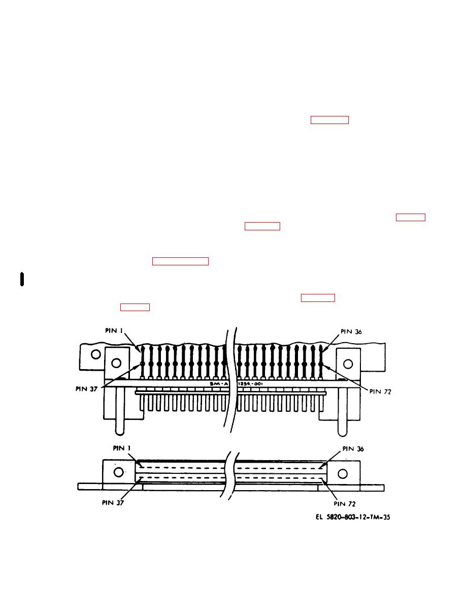
Figure 5-1. Typical PC card pin locations.
Change 2 5-3


