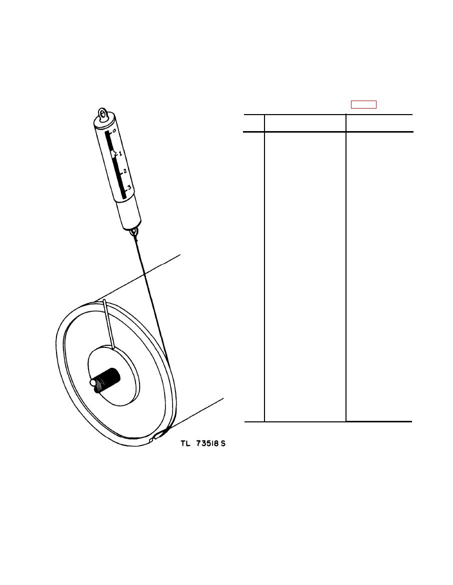
c. Clutch Assembly, Facsimile Sets AN/TXC-1,
Ref
Function
Name of put and description
symbol
Holds back drum while
CLUTCH ASSEMBLY:
Part of countershaft
drive assembly.
Stop arm and driver.
ARM, stop.
A
Retainer for friction
B
CLUTCH, ring.
driver plugs.
Driving part of clutch.
C
RING: composition,
clutch plates.
Driven part of clutch,
D
PLUG: composition,
clutch,
Clutch pressure
E
SPRING --------------
springs.
Clutch pressure
F
RETAINER, spring----
spring,
Clamps spring retain-
SCREW, clamp: No. 6-32
G
er to shaft.
Clutch assembly re-
H
RETAINER: clutch as-
tainer and clutch
sembly.
plate driver.
Hub for clutch as-
BEARING, clutch ------
I
sembly.
PIN, taper: 7/0---------
Secures clutch bear-
J
ing to drive shaft.
Holds clutch retain-
SCREW: No. 4-40 ftat-
K
head.
er to clutch bearing.
Transfers spring pres-
PLATE, pressure-- - - - -
L
sure to clutch.
Drives clutch assem-
M
SHAFT, drive ---------
bly.
N
Secondary clutch
CLUTCH: secondary,
bearing.
bearing.
SPRING, secondary
Secondary clutch*
0
clutch.
pressure.
Adjust pressure on
P
SCREWS: No. 4-40 . _.
secondary clutch.
Secondary clutch
ring.
ceiver TT-1C/TXC-1, serial numbers 1-165, Espey part
No. A21.771 replaces parts with reference symbols C and
H, shown above.


