TM 11-7440-278-14
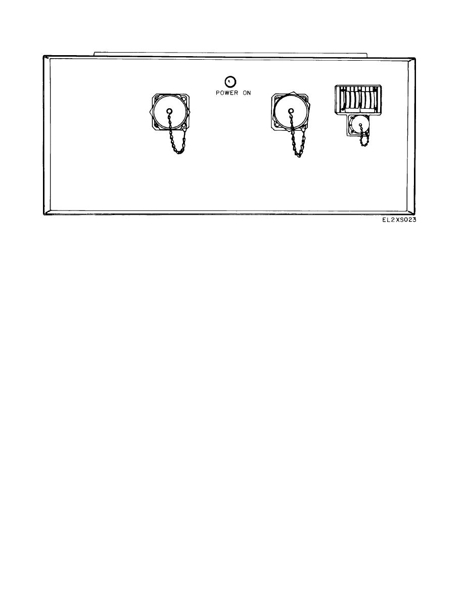
Figure 2-8. Prime Power Distribution Box for AN/MYK-8(V)3, Rear View
is properly installed and that all grounding connections
(3) Ensure that ventilation system is not
ale secure.
clogged or obstructed.
(2) Check to see that power cable connections
(4) Check all equipment for damaged indi-
are secure and that surplus cable is properly arranged.
cators, switches, controls, and connectors.
Section V.
INSTALLATION AND CIRCUIT LINEUP
move the braces before initiating the
2-15. Signal Connections
procedures below.
Intervan signal cables consist only of standard ADPE
cabling (fig. FO-2). These cables will be connected by
a. Check the OIL LEVEL gauge. The gauge must
qualified ADPE maintenance personnel.
indicate at least 1/2 full.
2-16. Movement of ADP Equipment to Operate
b. Clear flow between the rear of the rack and the
Position
van wall.
Data processing equipment within each van, except OL-
c. Depress the START MOTOR PUMP button on
88 (V)3 MYK-8(V), is connected to hy-draulic rams; the
the hydraulic console.
equipment is positioned in the center of the vans to
d. Depress and hold the console IN button. Hold
ensure stability during transit. Only OL-88(V) (3) /MYK-
the button until the equipment rack has stopped at the
8(V) is hard-mounted and swivels out 55 degrees to the
van wall. The OIL PRESS gauge will build up) to about
center of the van for transit and back to the walls for
600 pounds. Perform this step for each ADP unit to be
operation. Equipment may also be moved to facilitate
moved.
maintenance.
To retract the hydraulic mounted
e. Depress the STOP PUMP MOTOR button.
equipment for operation, proceed as follows:
f. Place hydraulic rail covers in place.
NOTE
2-17.
Post-Installation Operational Checks and
The equipment may be supported by
System Alignments
wooden braces during transit. If so, re-
Refer to the appropriate technical manuals listed in
appendix A.
2-10


