TM 11-7440-278-14
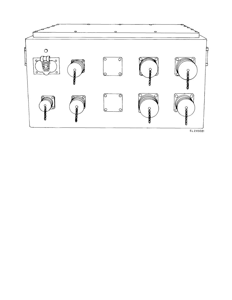
Figure 2-6. Prime Power Distribution Box for AN'/MUK-8(1')1.
operation. These checks consist basically of energizing
NOTE
the power and lighting circuits of the AN/ MIYK8(V) (*)
If audible/visual alarms are present,
assemblages and then performing a visual inspection of
remove power and check power
the equipment within each assemblage to ensure that no
connections at the prime
power
damage has occurred during transportation.
source for proper phasing. Do not
a. Power and Lighting Check
touch or remove any prime power
connector without first removing
NOTE
power.
Refer to figure 29 for locations of
controls and indicators referred to in
(6) Turn the ac service power main circuit breaker
the following procedures.
to ON.
(7) Turn incandescent lighting switch to ON in
(1) Ensure that all assemblages have been
each assemblage. Verify that each lighting system is
grounded and connected to the primary source (para. 2-
operative.
11, 2-12 and 2-13).
(8) Turn emergency and blackout circuit
(2) Ensure that the power source is deenergized
breakers to ON.
and that all circuit breakers and equipment switches are
(9) Turn fluorescent lighting circuit breakers to
in the OFF position.
ON. Confirm that all fluorescent lights are illuminated.
(3) Energize the I)rime power source.
(10) Energize utility outlet and air-conditioning
(4) Observe that ac service power panel phase
power circuit breakers in each assemblage.
lights are illuminated in each assemblage.
(11) 'Where applicable, energize hydraulic unit
(5) Observe that ADP power indicator and alarm
circuit breakers.
panel phase lights phase 1, phase 2, and phase 3 are
b. Visual Inspections..
illuminated in both vans.
(1) Check to see that the grounding system
2-8


