TM
11-5835-243-34/EE641-AA-MMl-010/E154
MTT/TO
31S3-4-110-1
tape motion is in the forward direction, DRIVE B
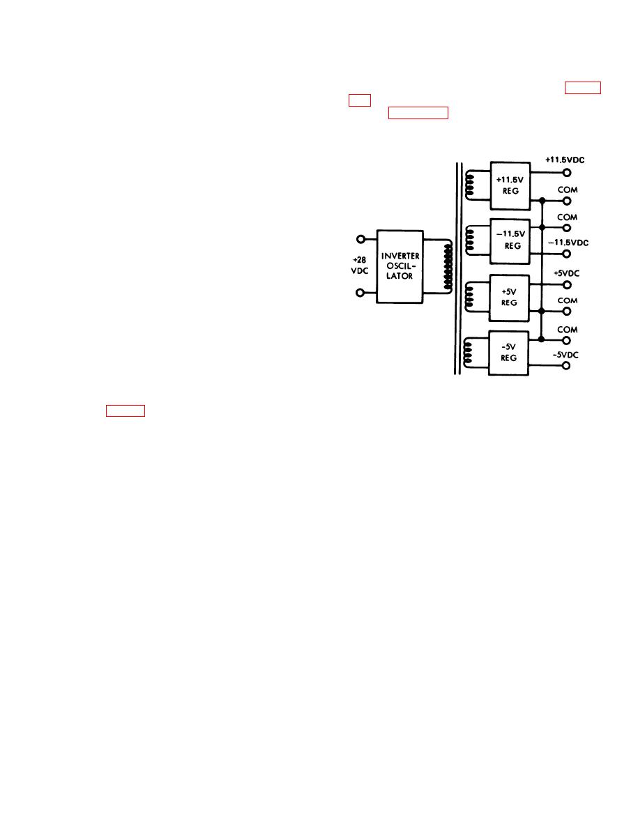
isolated transformer secondaries. The + 28-vdc
input power is chopped by the inverter/oscillator
goes positive, and the DRIVE A side of the bridge is
cut off. Operation of this side of the bridge is
and transformer coupled to four regulators. Figure
identical to the DRIVE A side described above. In
this manner the dc motor is driven linearly in either
supply. Figure 2-9 illustrates the tape transport
direction without the use of relays or other else
power and ground system.
tromechanical devices.
c. Power Turn-on. The junction field effect
transistors (JFETs) Q8 and Q9 restrict the motion
of the motor during power turn-on. R18 and C4 form
an RC network which controls the transistor gate
voltage. At startup, the positive side of C4 is at
ground. This turns Q8 and Q9 which hold the drive
signal transistors Q1 and Q7 in the cut off state,
creases, the gate voltages increase until Q8 and Q9
are turned off. In this state Q8 and Q9 present a
high impedence and do not interfere with normal
operation of the power amplifier circuitry.
d. Elapsed Time Meter. The elapsed time meter
on the front panel is energized when the capstan
motor operates. Transistor Q4 (part of the OR
circuit made up of Q4, CR3 and CR4) returns the
meter to ground when there is a positive voltage at
either of the motor terminals..
2-11. Power Supply Description
a. General. The tape transport power supply
EL4RD007
(PSI, fig. 1-2) is a sealed replaceable unit. The
power supply is a dc-to-dc converter type with
Figure 2-8. Power Supply Functional Block Diagram.
2-15


