TM
11-5835-243-34/EE641-AA-MMl-010/E154
MTT/TO
31S3-4-110-1
to the front panel via switch Q1. When BOT goes
high on the base of Q1, the transistor is turned on,
providing a path to ground for the BOT indicator.
With STRIP SENSE and LOW TAPE SENSOR
signals both present, BOT is inhibited and EOT is
enabled.
k. EOT Flip-Flop Logic. The end of tape flip-flop
logic U1 and U4 latches the EOT FF line high or low
in response to inputs derived from the forward and
reverse tape motion commands and the end of tape
(EOT) signal generated by the servo control logic.
EOT FF is initially at the logic low level with tape
moving in the forward direction. When LOW TAPE
SENSOR and STRIP SENSE are both high, in-
dicating that the strip at the end of the tape has
been sensed, EOT FF goes high and is latched.
When HOLE SENSE then goes high, the END
HOLE output line goes high and the tape motion
command decode logic on control logic circuit card
A4 commands fast reverse (FAST RVS). When the
strip is again sensed in the reverse direction, flip-
flop U4 is reset, latching EOT FF low. This con-
ditions the logic to respond to beginning of tape
(BOT) signals at the end of the rewind cycle.
l. Switch Noise Buffering. Switch contact noise
EL4RD013
generated by the front panel RWND switch is
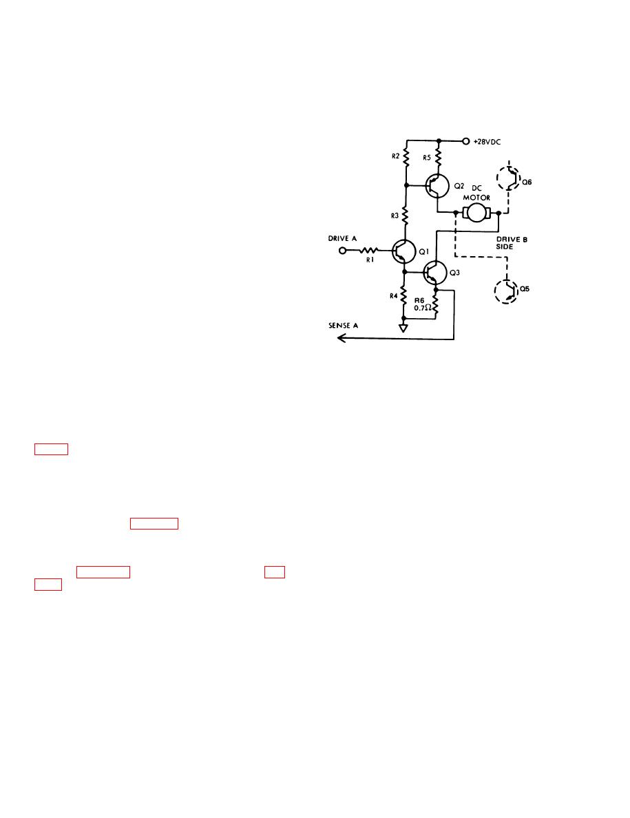
Figure 2-7. Bridge Amplifier Simplified Schematic Diagram.
buffered by flip-flop U1. The signal RWND SW is a
logic high level when the switch is depressed.
b. Bridge Amplifier. When tape motion is in the
reverse direction, DRIVE A receives a positive
2-10. Power Amplifier Circuit Description
servo error signal from the servo control circuit
a. General. The power amplifier assembly (A9,
card. DRIVE B, at this time, is a negative voltage
which cuts off the opposite half of the bridge.
loop. The power amplifier is controlled by the error
Transistor Q1 linearly amplifies the error signal to
signal generated on the servo control circuit card
drive transistor Q2 which, in turn, supplies current
A5, and provides the necessary current to drive the
to the capstan motor. Transistor Q3 is also driven
capstan motor at normal or fast speed in both the
into saturation by Q1, providing a ground return for
forward and reverse directions. As illustrated in the
the motor current via the 0.7-ohm resistor R6. The
schematic diagram (fig. FO-6), the power amplifier
voltage developed across R6 is fed back to the
is basically a bilateral bridge amplifier working in
current sense amplifier on the servo control circuit
the Class B mode. While one side of the bridge is
card (SENSE A) in order to control the voltage to
operating as a linear amplifier, the other side is cut
current gain (transconductance) of the power am-
off. Use figure 2-7 and the schematic diagram (fig.
plifier. This forms a closed current-gain loop. When
2-14


