TM 11-5805-424-15/NAVELEX 0967-220-9010/TO 31W2-2G-41
7-6. Data Test
a. Test Equipment and .Material.
See Maintenance Allocation Chart Section
III for test equipment.
b. Test Connections and Conditions.
(1) Remove the test MD-4(P)/G from its case and install the repaired MD-674(P)/G in its place, or remove the appropriate plug-in module from the test
MD-474(P)/G, and install the repaired plug-in module in its place
(2) Connect the equipment as shown in A and B, figure 7-1.
(3) Adjust DD-205A controls to obtain test pattern on screen.
(4) Strap together only terminals 5 and 6, on the bottom of the harness card.
(5) Strap together terminals 1, 2, and 3, on PC a ,assembly AS.
(6) Strap together terminals 2 and 4 on PC assembly All.
(7) Operate all POWER switches to the on position.
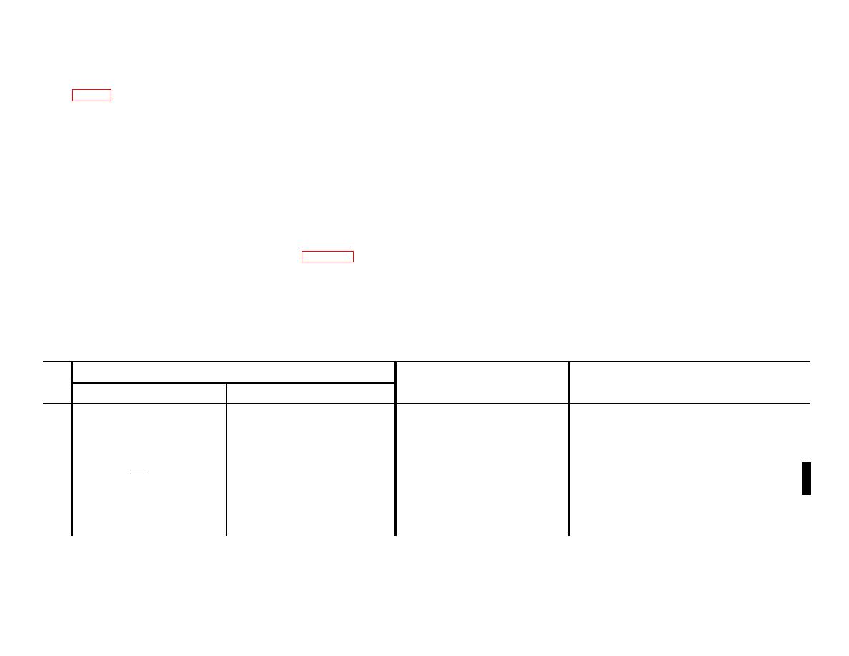
c. Procedure.
Control settings
Step
No.
Procedure
Performance standard
Test equipment
Equipment under test
1
PG-205A
BAUD RATE: As required.
a. Rotate OUTPUT LEVEL
a. ME-30A/U should indicate between
ALARM: DISABLE.
ADJ control from one ex-
-20 dbm and +3 dbm; DD-205A
INPUT: 600Ω.
CHARACTER RELEASE:
treme to the other.
SIGNAL lamp should light and
OUTPUT: 600Ω.
FREE RUN.
meter should indicate less than 3.5%
DISTORTION: OFF.
INPUT SELECT: DATA.
distortion (2% for MX-7379/G).
37.5
b. Adjust OUTPUT LEVEL
b. None.
EXTERNAL: -1200
ADJ control for 0 dbm on
PATTERN SELECTOR:
ME-30A/U, or equivalent.
REVERSALS.
c. Operate INPUT SELECT
c. Electronic Counter 5233L should indi-
BAUDS: As required.
switch to MARK.
cate as follows for each MX-73(*)/
JACK SIGNAL SELECTOR:
G ( 0.5 cps):
LOW LEVEL.
MX-7372/G: 425 cps.
Change 6
7-3


