TM 5-4920-410-13&P
(9) Disconnect all test equipment from test set and
set test set switches to down or OFF.
i. Panel Point of Regulation.
(1) Observe that the 400 GEN T1 circuit breaker
is OFF and test set switches are down or OFF.
(2) Connect 115 vat, 400 Hz to J1 connector pins A
(+) for T1 and pin S ( -) and connect digital voltmeter to
J1 connector pins T (+) and S (-).
(3) Push 400 GEN T1 circuit breaker to IN position
and place GEN switch to OFF.
(4) Set DC BACKUP to ON and CT CURRENT
switch to OFF.
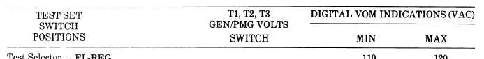
(5) Set GEN/PMG VOLTS switch to T1 and TEST
SELECTOR to each position as listed in Table 4-5. Indica-
tions will be as specified in Table 4-5.
(6) Pull 400 GEN T1 circuit breaker to OUT po-
sition.
(7) Repeat techniques 2, 3, 5, & 6 above for
GEN/PMG VOLTS switch T2, J1 connector pin U (+),
and set TEST SELECTOR to each position as listed in Ta-
ble 4-5. Indications will be as specified. If not, see
troubleshooting Table 4-7.
(8) Repeat technique 2, 3, 5, & 6 above for
GEN/PMG VOLTS switch T3, J1 connector pin V (+)
and set TEST SELECTOR to each position as listed in
Table 4-5. Indications will be as specified. If not, see
troubleshooting Table 4-7.
(9) Disconnect all test equipment, jumpers from
test set and place all switches to down or off position.
j. Current Limit Resistance Check.
(1) Remove all test equipment from test set.
(2) Connect digital VOM to J1 pins A and N and set
range to ohms.
Table 4-5. Panel Point of Regulation
4 -8