(3) Set CT CURRENT READ switch to OFF and
TEST SELECT to AØ DC CT position.
(4) Connect 28 vdc power supply to J1 pins S(-) and
J (+) and push 400 Hz circuit breaker to IN.
(5) Set current limit 30 KVA/20 KVA to 20 KVA.
Digital VOM will indicate 24 ohms. If not, see
troubleshooting Table 4-7.
(6) Set current limit 30 KVA/20 KVA to 30 KVA.
Digital VOM will indicate 14 ohms. If not, see
troubleshooting Table 4-7.
(7) Set current limit 30 KVA/20 KVA to OFF and
set FF GO/NO GO to NO GO. Digital VOM will indicate
2K ohms. If not, see troubleshooting Table 4-7.
(8) Set FF switch to GO. Digital VOM will indicate
4K ohms. If not, see troubleshooting Table 4-7.
(9) Disconnect all test equipment from test set and
set all test switches to down or OFF.
k. Regulation TRIAC Isolation Procedure.
(1) Pull 400 GEN TI circuit breaker to OUT
position.
TM 55-4920-410-13&P
(2) Remove circuit board assembly A2 and reinstall
using extender board.
(3) Connect equipment as shown in Figure 4-2 (DC
power supply not connected).
(4) Push 400 GEN TI circuit breaker to IN
position.
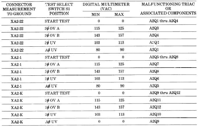
(5) Perform voltage checks Table 4-6using TEST
SELECT switch at positions and test points specified.
Indications will be as specified. If not, see troubleshoot-
ing Table 4-7.
(6) Disconnect all test equipment from test set and
set test switches to the down or OFF position.
1. Underfrequency Circuit.
(1) Set dc power supply to OFF and disconnect fre-
quency counter from equipment setup.
(2) Connect frequency counter and oscilloscope to
J5 UFCAL, using adapters, cables, and X10 probes.
NOTE
Connect probes to frequency counter INPUT.
Table 4-6. Point of Regulation TRIAC Isolation Procedure
4-9


