TM 5-2420-224-20-2
F L O O R P L A T F O R M R E P L A C E M E N T ( C O N T )
3.
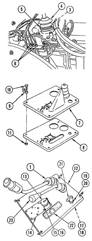
I F N E W B E L L O W S w a s i n s t a l l e d ,
CAREFULLY ROLL protective BELLOWS (4)
over cover (3), TIGHTEN CLAMP (5), and
CONNECT three air HOSES (6).
4.
INSTALL COVER (7) on cover plate (8).
5.
INSTALL four HANDLES (9), four bolts (10),
and four nuts (11).
6.
INSTALL access COVER assembly (12) and
CAREFULLY PULL BELLOWS (1) and
STE/lCE-R CONNECTOR (13) through
opening.
7.
INSTALL COVER (14), four screws (15), four
nuts (16), and STE/lCE-R connector (13).
8.
INSTALL BELLOWS (1) in access cover
assembly (12).
9.
INSTALL washer (17), all wheel selector
VALVE (18), washer (19), and nut (20).
10. INSTALL LEVER (21) and two knobs (22 and
23).
NOTE
Follow-on Maintenance:
Install main disconnect switch
(page 4-171).
Lower cab (page 4-418).
4-436

