TM 5-2420-224-20-2
C A B T I L T A N D L O W E R ( C O N T )
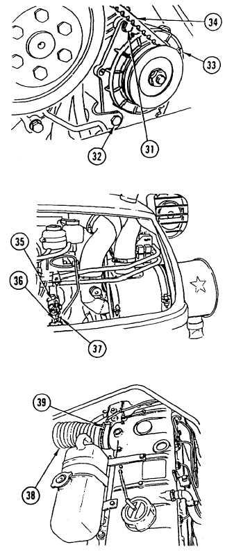
22. LOOSEN two SCREWS (31 and 32) and
MOVE ALTERNATOR (33) outward. APPLY
thumb PRESSURE on belt and CONTINUE
TO TIGHTEN until bow in belt is 0.39-0.59 in.
(10-15 mm).
23. TIGHTEN two SCREWS (31 and 32).
•
•
NOTE
Position screw so flat side of
universal joint will prevent screw
from turning.
Make sure front wheels are
centered before performing step
24.
24. CONNECT steering column universal JOINT
(35) and INSTALL SCREW (36) and new nut
(37). TIGHTEN to 24 Ib-ft (32 N.m).
25. CONNECT air intake BELLOWS (38) and
TIGHTEN CLAMP (39).
26. REMOVE cab SUPPORT installed in step 6
and BAR installed in step 5.
NOTE
Follow-on Maintenance:
Install inside engine hood (page
4-389).
Install outside engine hood (page
4-388) .
I n s t a l l c a n o p y ( F O P S ) ( p a g e
4-387).
Install spare tire and mount (SEE)
(page 4-390).
I n s t a l l s p a r e t i r e a n d m o u nt
(HMMH) (page 4-391).
Install front loader (SEE) or forklift
(HMMH) (page 4-794 or 4-546).
Connect batteries (page 2-24).
4-432


