TM 5-2420-224-20-2
F L O O R P L A T F O R M R E P L A C E M E N T
This task covers: a. Removal b. Installation
I N I T I A L S E T UP
Tools and Special Equipment:
General Safety Instructions:
TOOl Kit, SC 5180-90-CL-N26
Equipment Condition:
Reference
Condition Description
Page 4-418
Cab Tilted
Page 4-171
Main Disconnect Switch
Removed
Page 2-23
Air Pressure Relieved
W A R N I N G
D o n o t d i s c o n n e c t a n y a i r
system lines or fittings unless
vehicle engine is shut off and
air system pressure is relieved.
To do so could result in injury
to personnel.
R E M O V A L
1.
2.
3.
4.
5.
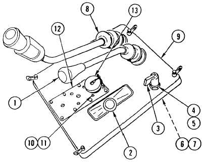
REMOVE two KNOBS (1 and 2) and LEVER (3).
REMOVE nut (4), washer (5), all wheel selector VALVE (6), and washer (7). SET all wheel selector
VALVE ASIDE.
REMOVE BELLOWS (8) from access cover assembly (9).
REMOVE four nuts (10), four screws (11), and COVER (12).
REMOVE access COVER assembly (9) and CAREFULLY PUSH BELLOWS (8) and STE/lCE-R
CONNECTOR (13) through access cover assembly (9).
4-433

