TM 11-5805-424-15/NAVSHIPS 0967-220-9010/TO 31W2-2G-41
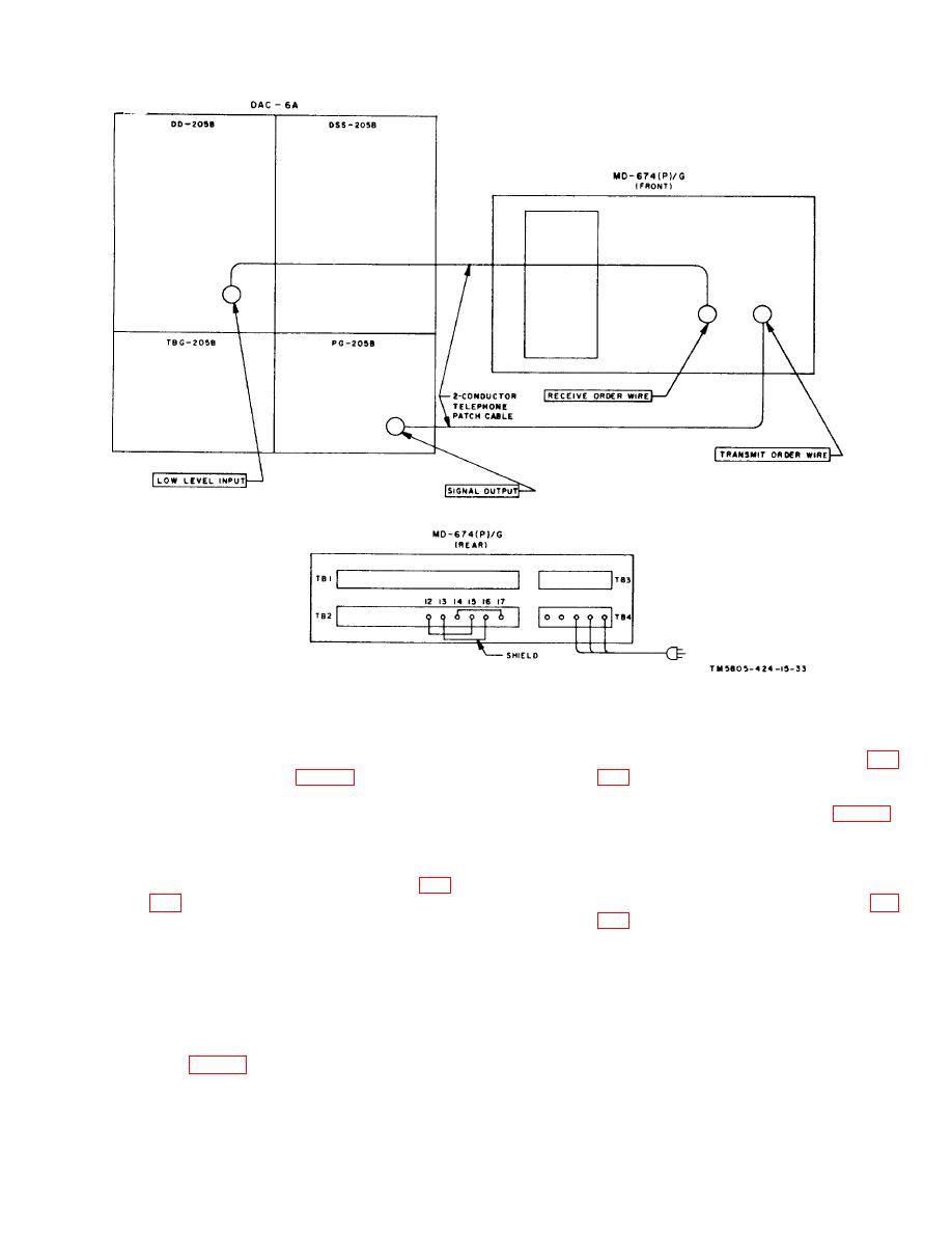
Figure 6-1. Operational tests, connection diagram.
no-transition alarm send terminals and the
no-transition alarm receive terminals at
(6)
Operate the INPUT SELECT switch (fig.
the rear of the unit (fig. 2-2). Plus 6 volts
should be measured at the loss-of-
from the balanced receive carrier input
transmit-carrier alarm terminals and the
terminals at the rear of the unit (fig. 2-2).
loss-of-receive-carrier alarm terminals at
The ALARM indicator lamp should light,
the rear of the unit.
and a ground (O volt) should be measured
at the no-transition alarm receive
(4)
Operate the INPUT SELECT switch (fig.
terminals and the loss-of-receive carrier
alarm terminals at the rear of the unit (fig.
in (3) above.
the no-transition alarm send terminals and
(5)
Operate the INPUT SELECT switch to
the
loss-of-transmit-carrier
alarm
OFF. In addition to the indications in (3)
terminals at the rear of the unit. The
above, a positive 6 volts should be
DSS-205A should indicate a steady mark.
measured at the loss-of-transmit-carrier
alarm terminals and at the loss-of receive-
(7)
Reconnect the lead to the balanced
carrier alarm terminals at the rear of the
receive carrier input terminals.
The
unit (fig. 2-2).
ALARM in-
6-5


