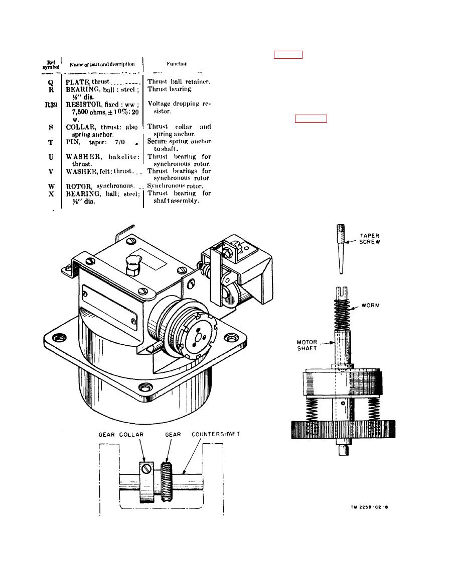
shaft can be replaced if suitable shop facilities are
available. Pin the new gear to the shaft with a
taper pin. Sometimes, a damaged gear can be
moved along the shaft and pinned in a new place
so that 23 good portion of the gear will mesh with
the worm.
return spring (H) must produce a strong spring
action. Replace the spring if the tension is too
weak. Pivots (F) and (G) must not cause binds
or side play. To adjust the armature backstop
(B), set up the transceiver for a receiving test
on a phasing signal. Proceed as follows: With
the PHASE button depressed, back off the ad-
justing screw until the armature fails to operate.
Screw in the armature back screw until the arma-
ture fails to catch the top arm. Return the screw
Figure 106. Synchronous motor, KBA-2.
146


