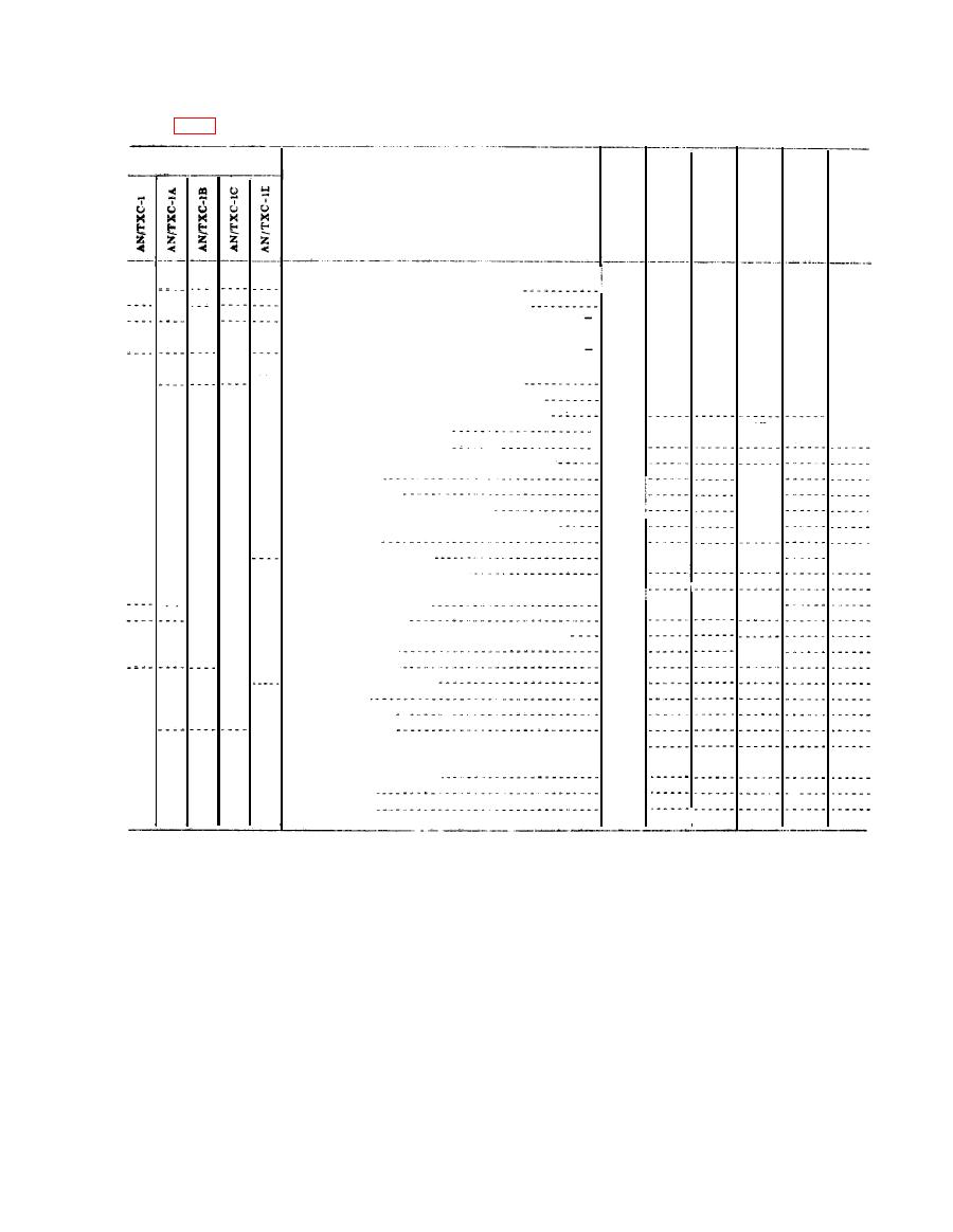
7. Table of Components
(figs 1-6)
Facsimile set
Unit
Required
Height
Depth
Length
Volume
Component
weight
(in.)
No.
(cu ft)
(in.)
(in.)
(lb)
Facsimile Transceiver TT-1/TXC-1
17 5/8
1
10
34 5/8
3.5
(*)
85
(*)
Facsimile Transceiver TT-1A/TXC-1
17 5/8
1
10
34 5/8
3.5
85
(*)
Facsimile Transceiver TT-1B/TXC-1 or TT
17 5/8
34 5/8
1
10
3.5
85
1C/TCC-1.
(*)
Facsimile Transceiver TT-1D/TXC-1 or TT
17 5/8
34 5/8
10
1
3. 5
85
1E/TXC-1.
17 5/8
Facsimile Transceiver TT-1F/TXC-1
34 5/8
1
10
85
3.5
(*)
(*)
(*)
Rectifier Power Unit PP-86(*)/TXC-1
9
10
12
62
1
48
(*)
(*)
(*)
(*)
(*)
(*)
(*)
(*)
Photographic Equipment PH-549/TXC-1
1
83
(*)
(*)
(*)
(*)
Table MT-252(*)/TXC-1
32
22
4.7
1
37
86
(*)
(*)
(*)
(*)
(*)
Paper, direct recording
1
(*)
(*)
(*)
(*)
(*)
Paper, direct recording, hectograph process
1
(*)
(*)
(*)
Cord CD-1018
1
120
(*)
(*)
(*)
(*)
(*)
(*)
Cord CD-1019
1
96
(*)
(*)
(*)
(*)
(*)
Cable assembly, special purpose
1
66
(*)
(*)
(*)
(*)
(*)
Cable assembly, special purpose, electrical
1
6
(*)
(*)
(*)
(*)
Clips, alligator
2
(*)
(*)
(*)
(*)
(*)
(*)
4
Coupler, induction, UC
1
2
6
18
(*)
(*)
(*)
(*)
Cover, dust (transceiver)
1
(*)
(*)
(*)
(*)
(*)
Cover, dust (power unit)
1
(*)
(*)
(*)
1
2
L o u d s p e a k e r LS-11
4
4
(*)
(*)
(*)
1
Lamp LM-52
(*)
(*)
(*)
(*)
(*)
(*)
(*)
Weighing scale 2 to 24 ounces (avoirdupois)
1
(*)
(*)
Screw driver
1
2
(*)
(*)
(*)
Wrench, Allen #6
1
(*)
(*)
(*)
(*)
(*)
Wrench, TL-507/U
1
(*)
(*)
(*)
(*)
2
TM 11-2258
(*)
(*)
(*)
(*)
(*)
Tube extractor
1
(*)
(*)
(*)
6
Fuse, 3 amperes
Blower and dust filter assembly including filter
5
bag.
Can of activated carbon
2
Flexible hose
1
2
Hose clamps
Note. This list is for information only.
See appropriate supply publications for information pertaining to requisi-
tioning of spare parts.
side, back, or top for inspection and repair.
Mounted to the chassis are the motor assembly,
a. Facsimile Transceiver TT-1(*)/TXP-1. All
bearings that support the lead screw and drum,
models of Facsimile Transceiver TT-1(*)/TXC-1
fork oscillator unit, regulator unit, signal and
are similar in size, weight, and appearance. They
phasing circuit components, transmitting optical
differ slightly in the number of operating controls
system, receiving optical system, indicating
and in certain circuit features. The transceiver
meters, and various other components. The
is mounted on a steel chassis 345/8 inches long,
power supply connection plug and the panel sup-
175/8 inches deep, and 10 inches high. Tubular
porting the operating controls and terminal panel
guards, 1 inch in diameter, are welded to each end
also are mounted on the chassis. Operating con-
of the chassis to serve as carrying handles and to
protect the equipment when it is turned on its
trols are located on a sloping portion of the front


